Sewage treatment system

A technology of sewage treatment system and aeration system, which is applied in the field of new sewage treatment process system, can solve the problems of inability to maintain high concentration, limit biochemical reaction efficiency, and high operating energy consumption cost, achieve good effluent quality, reduce investment and operation Cost, efficient and stable operation

Active Publication Date: 2010-05-12
北控水务(中国)投资有限公司
View PDF0 Cites 19 Cited by
  • Summary
  • Abstract
  • Description
  • Claims
  • Application Information

AI Technical Summary

Problems solved by technology

[0004] Both the traditional AAO process and the MBR process have certain defects
In the AAO process, denitrification and phosphorus release compete for carbon sources in an anaerobic environment; due to the solid-liquid separation requirements of the secondary settling tank and the influence of sludge bulking and other factors, the sludge in the aeration tank cannot maintain a high concentration and thus limits biochemical reaction efficiency
In the MBR process, membrane fouling is prone to occur, resulting in a continuous decrease in membrane flux, which seriously affects the treatment efficiency; high membrane loss, high operating energy consumption, and high operating costs
[0005] Some improved MBR processes have emerged, such as the combination of the traditional oxidation ditch process and the MBR process. Although the internal reflux is set by combining the membrane treatment process, thereby enhancing the effect of nitrogen and phosphorus removal, this process has not solved the problem of the membrane reaction process. The main defects, namely "membrane fouling easily and high energy consumption cost of operation", etc., how to reduce the operation and maintenance costs under the premise of ensuring the quality of the effluent is the development direction of the MBR improved process

Method used


Image

  • Sewage treatment system
  • Sewage treatment system
  • Sewage treatment system

Examples


example

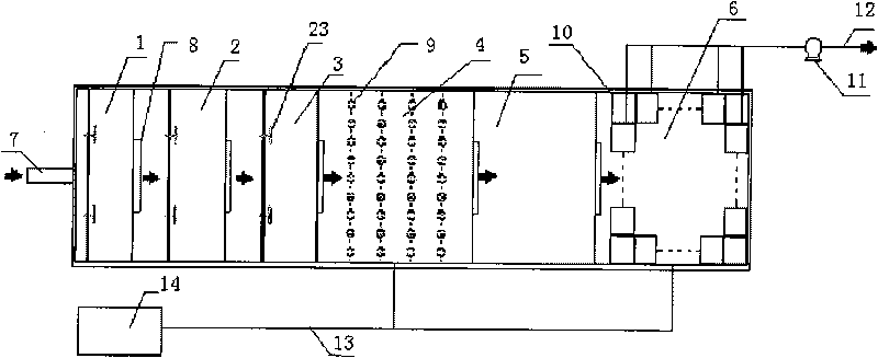
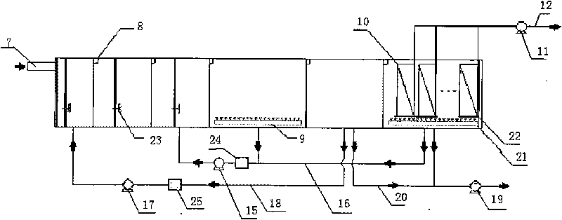
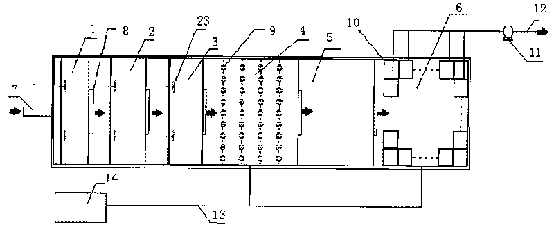
[0031] see figure 1 and figure 2, a sewage treatment system, comprising selection zone 1, anaerobic pool 2, anoxic pool 3, aerobic pool 4, sedimentation adjustment pool 5, aerobic membrane pool 6, water inlet 7, water outlet weir 8, aeration system 9 , membrane block 10, outlet pump 11, outlet pipe 12, air pipe 13, blower 14, mixed liquid return pump 15, mixed liquid return pipe 16, sludge return pump 17, sludge return pipe 18, excess sludge pump 19 , excess sludge pipe 20, aerobic membrane tank aeration system 21, membrane block backwashing device 22, plug flow agitator 23, mixed liquid backflow automatic control device 24, sludge backflow automatic control device 25; selection area 1, Anaerobic pool 2, anoxic pool 3, aerobic pool 4, sedimentation regulating pool 5, and aerobic membrane pool 6 are connected successively through the outlet weir 8; push flow is provided in selection area 1, anaerobic pool 2, and anoxic pool 3 Agitator 23; aerobic tank 4 and aeration system ...


PUM


Abstract

The invention discloses a sewage treatment system, which comprises a selection area, an anaerobic tank, an anoxic tank, an aerobic tank, a precipitation adjusting tank and an aerobic membrane tank, which are connected in turn through an effluent weir, wherein the precipitation adjusting tank is arranged between the aerobic tank and the aerobic membrane tank. The sewage treatment system is technically characterized in that the system has two-stage oxidation and the precipitation adjusting tank is arranged between the aerobic tank and the aerobic membrane tank, so the membrane loss is greatly reduced, the membrane flux of the membrane tank is ensured, and the impact resistant loading capacity of the system is obviously improved while reducing the running cost; basically the consumption of the membrane is saved, and meanwhile the treatment efficiency of AA0 is improved; and composition units of the process device are built integrally in sequence and the units share the same wall, so the design can save investment and save space, and meanwhile the running cost can also be saved due to interconnection of the units. The integral device has low investment and running costs and ultrahigh yield water quality, and is particularly suitable for the requirements of water-lacking large and medium cities for recycling sewage.

Description

technical field [0001] The invention relates to a sewage treatment process, in particular to a new sewage treatment process system combining "anaerobic-anoxic-aerobic" (AAO) technology and membrane biotechnology (MBR). Background technique [0002] The AAO biological nitrogen and phosphorus removal process is the anaerobic (A)-anoxic (A)-aerobic (O) activated sludge method, which was developed by American experts in the anaerobic-aerobic (AO) method in the 1970s. Developed on the basis of the technology, it is a simultaneous denitrification and phosphorus removal process widely used at home and abroad. The mechanism is: the sewage is degraded through the anaerobic pond-anoxic pond-aerobic pond in turn. The main function of the anaerobic tank is to release phosphorus and oxidize some organic matter at the same time; the main function of the anoxic tank is to remove nitrogen; the aerobic tank has multiple functions to remove BOD 5 , nitrification and phosphorus uptake reacti...

Claims


Application Information

Patent Timeline
Patent Type & Authority Applications(China)
IPC IPC(8): C02F9/14C02F3/30
Inventor 侯锋薛晓飞邵彦青张振鹏
Owner 北控水务(中国)投资有限公司
Why Eureka
Try Eureka