LLC resonant converter control method, synchronous rectification control method and device

A technology of resonant converter and control method, applied in the field of communication, can solve problems such as large loss and unstable output voltage, and achieve the effects of reducing loss, reliable use, and simplifying peripheral hardware circuits

Inactive Publication Date: 2010-05-12
ZTE CORP
View PDF0 Cites 66 Cited by
  • Summary
  • Abstract
  • Description
  • Claims
  • Application Information

AI Technical Summary

Problems solved by technology

[0008] The present invention is proposed aiming at the problems of unstable output voltage, large loss, and common defects of the synchronous rectification scheme. Therefore, the main purpose of the present invention is to pr...

Method used


Image

  • LLC resonant converter control method, synchronous rectification control method and device
  • LLC resonant converter control method, synchronous rectification control method and device
  • LLC resonant converter control method, synchronous rectification control method and device

Examples


example 1

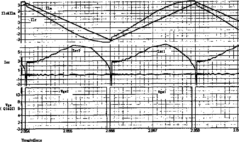
[0049] Figure 3 to Figure 6 yes figure 1 The LLC resonant circuit shown shows the waveforms of primary side power tube drive, secondary side rectification current, resonant current and excitation current under different frequency bands and different loads.

[0050] specifically, image 3 is f≥f according to Example 1 s Timing diagram of the light load signal, the waveforms in the figure from top to bottom are: primary resonance current and excitation current, secondary rectification current, main switch drive; Figure 4 is f≥f according to Example 1 s The time sequence diagram of the heavy load signal, the waveforms in the figure are from top to bottom: primary resonance current and excitation current, secondary rectification current, main switch drive; Figure 5 is f according to Example 1 m s Timing diagram of the light load signal, the waveforms in the figure from top to bottom are: primary resonance current and excitation current, secondary rectification current, mai...

example 2

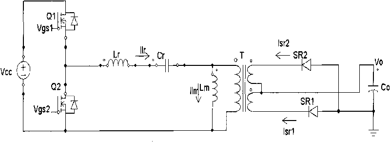
[0055] Figure 7 It is a structural schematic diagram of the control device applied according to the LLC resonant converter control method and the synchronous rectification control method of Example 2, as Figure 7 As shown, the control device is composed of a sampling feedback circuit 301, a controller 302, and driving circuits 303-305. The controller 302 uses a digital signal processor (DSP) to output the control signals required by the primary side power switch and the synchronous rectification switch, and the driving circuits 303-305 convert the control signals into driving signals capable of driving the power switches.

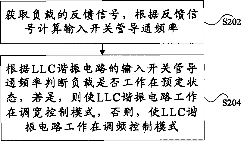
[0056] Figure 8 It is a flow chart of generating the primary side power switch control signal according to Example 2, such as Figure 8 As shown, the generation process of the primary side power switch control signal includes the following steps 801 to 807:

[0057] Step 801, calculating the voltage error: the output voltage of the LLC resonant circui...


PUM


Abstract

The invention discloses an LLC resonant converter control method, synchronous rectification control method and device, wherein the LLC resonant converter control method comprises the steps of: judging whether a load works in a preset state or not according to the connection frequency of an input switching tube of an LLC resonant circuit; if the load works in the preset state, enabling the LLC resonant circuit to work in a width modulation mode, and otherwise, enabling the LLC resonant circuit to work in a frequency modulation mode, wherein the preset state comprises a light load state or no-load state. The invention realizes the voltage stabilization under the condition of light load or no-load of the LLC resonant circuit, lowers the circuit loss, effectively simplifies a peripheral hardware circuit, and is more reliable in use compared with the prior art.

Description

technical field [0001] The present invention relates to the communication field, in particular to a control method for an LLC resonant converter, a synchronous rectification control method, a controller for an LLC resonant converter, and a synchronous rectification control device. Background technique [0002] With the development of switching power supply technology, high efficiency and high power density have become the development trend. In this case, LLC resonant circuits are more and more widely used in the industry. Compared with other soft switching technologies, the LLC resonant circuit has some obvious advantages: it can realize the zero-voltage turn-on of the primary side switch tube in a relatively wide frequency range, and has better power-down maintenance time characteristics; because the secondary side The rectifier tube is turned off with zero current, so the turn-off loss of the rectifier tube is reduced; the high operating frequency of the circuit can reduc...

Claims


Application Information

Patent Timeline
IPC IPC(8): H02M3/335
CPCY02B70/1475Y02B70/1433H02M3/33507H02M3/33592Y02B70/10Y02P80/10
Inventor 司徒琴李俊凯刘辉
Owner ZTE CORP
Why Eureka
Try Eureka