
Silicon crystal growing device with two-way airflow

A growing device and silicon crystal technology, which is applied in the field of crystal growth into single crystal and silicon polycrystalline melting, can solve the problems of high production cost, abnormal growth, broken edges, etc., and achieve the effect of reducing corrosion, reducing contact area and time

Inactive Publication Date: 2010-05-26
芜湖升阳光电科技有限公司
View PDF0 Cites 8 Cited by
  • Summary
  • Abstract
  • Description
  • Claims
  • Application Information

AI Technical Summary

Problems solved by technology

The processing technology and production scale of graphite thermal systems currently used for silicon single crystal growth are in the leading position in the world in my country. However, in the design of graphite thermal systems for growing large-sized single crystals, abnormalities often occur during the growth of single crystals. Growth, broken edges and many other situations have caused the growth of large-size silicon single crystals to remain in a blind spot in China. Although there are very few companies that can barely grow, the cost of operation and production is too high, which does not meet the purpose of comprehensive economic benefits of the enterprise. Can not be recognized and popularized by the market; the entire domestic industry is still growing silicon single crystals of 6 inches and below, but the demand for silicon single crystals of 8 inches and above in foreign markets is increasing day by day, how to design and grow large diameters above 8 inches The thermal system of silicon single crystal is imminent

Method used


Image

  • Silicon crystal growing device with two-way airflow
  • Silicon crystal growing device with two-way airflow

Examples


Embodiment Construction

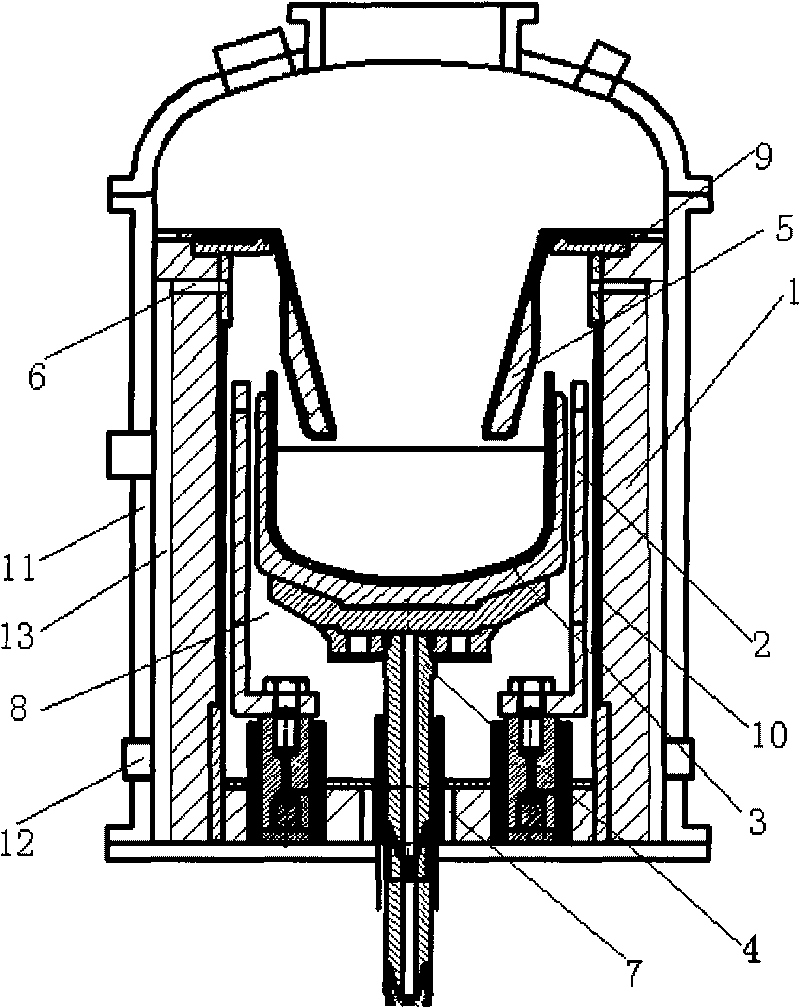
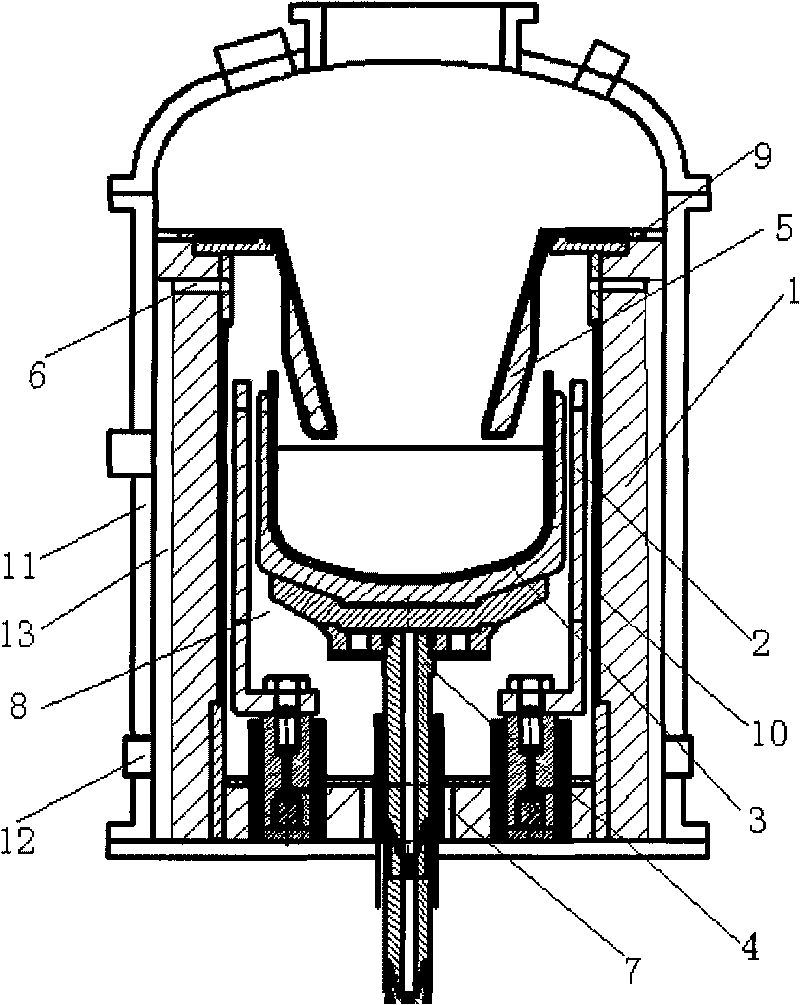
[0013] Referring to the accompanying drawings, the silicon crystal growth device with two-way air flow includes a furnace body 1, an upper insulation cylinder 9 is arranged on the inner wall of the furnace outside the guide cylinder 5, and a lower insulation cylinder 10 is arranged on the lower inner wall of the furnace body. A cylindrical heater 2 is placed in the inner cavity of the furnace body 1, and the two electrodes at the bottom of the heater 2 are respectively embedded in the bottom of the furnace body 1. A graphite crucible 3 is arranged in the inner cavity of the heater 2, and the graphite crucible 3 passes through the furnace The connecting rod 4 at the bottom of the body 1 is supported and fixed, and the upper opening of the body of furnace 1 is placed with a guide tube 5 that can extend into the inner cavity of the graphite crucible 3, and an exhaust port 6 is arranged on the side wall of the top of the body of furnace 1, and There is an argon gas inlet 7 at the b...


PUM


Abstract

The invention discloses a silicon crystal growing device with two-way airflow, which comprises a furnace body; an inner cavity of the furnace body is provided with a cartridge heater inside; two electrodes at the bottom of the heater are respectively embedded into the bottom of the furnace body; the inside of the inner cavity of the heater is provided with a graphite crucible which is supported and fixed by a connecting rod passing through the bottom of the furnace body; an upper opening of the furnace body is provided with a guide cylinder capable of extending into an inner cavity of the graphite crucible; the side wall on the top of the furnace body is provided with a vent, and the bottom of the furnace body is provided with an argon inlet; the vent is communicated with the argon inlet through a gap between the inner wall of the heater and the outer wall of the graphite crucible; a gas cylinder is sleeved outside the furnace body; the side wall at the bottom of the gas cylinder is provided with an outlet; and the outlet is communicated with the vent through a gap between the gas cylinder and the furnace body. The silicon crystal growing device adopts the two-way airflow, the corrosion of harmful gases in the thermal field to graphite pieces can be reduced, and the contact area and contact time of oxygen and graphite are decreased, so that carbon oxides and the harmful gases on the surface of silicon liquid are quickly taken way from a thermal system under the driving of the flow direction of lower gases, and the carbon content in the crystal is effectively controlled.

Description

technical field [0001] The invention relates to the field of silicon polycrystal melting and crystal growth into single crystal, in particular to a silicon crystal growth device with two-way gas flow. Background technique [0002] Czochralski method CZ Czochralski single crystal method, through resistance heating, polycrystalline silicon in a quartz crucible is melted, and the temperature is kept slightly higher than the melting point of silicon, under the protection of an inert gas, after seeding, shouldering , shoulder turning, equal diameter, finishing, crystal removal and other steps to complete the crystal growth. The larger the size of the growing single crystal, the higher the requirements on the graphite thermal system. The processing technology and production scale of graphite thermal systems currently used for silicon single crystal growth are in the leading position in the world in my country. However, in the design of graphite thermal systems for growing large-s...

Claims


Application Information

Patent Timeline
IPC IPC(8): C30B15/00C30B27/02
Inventor 马四海张笑天
Owner 芜湖升阳光电科技有限公司
Learn More