

Flue gas purification method
A flue and air flow technology, applied in chemical instruments and methods, separation methods, air quality improvement, etc., can solve the problems of inefficient removal of sulfur trioxide or sulfuric acid aerosol, complexity of smoke flow control, etc.
- Summary
- Abstract
- Description
- Claims
- Application Information
AI Technical Summary
Problems solved by technology
Method used
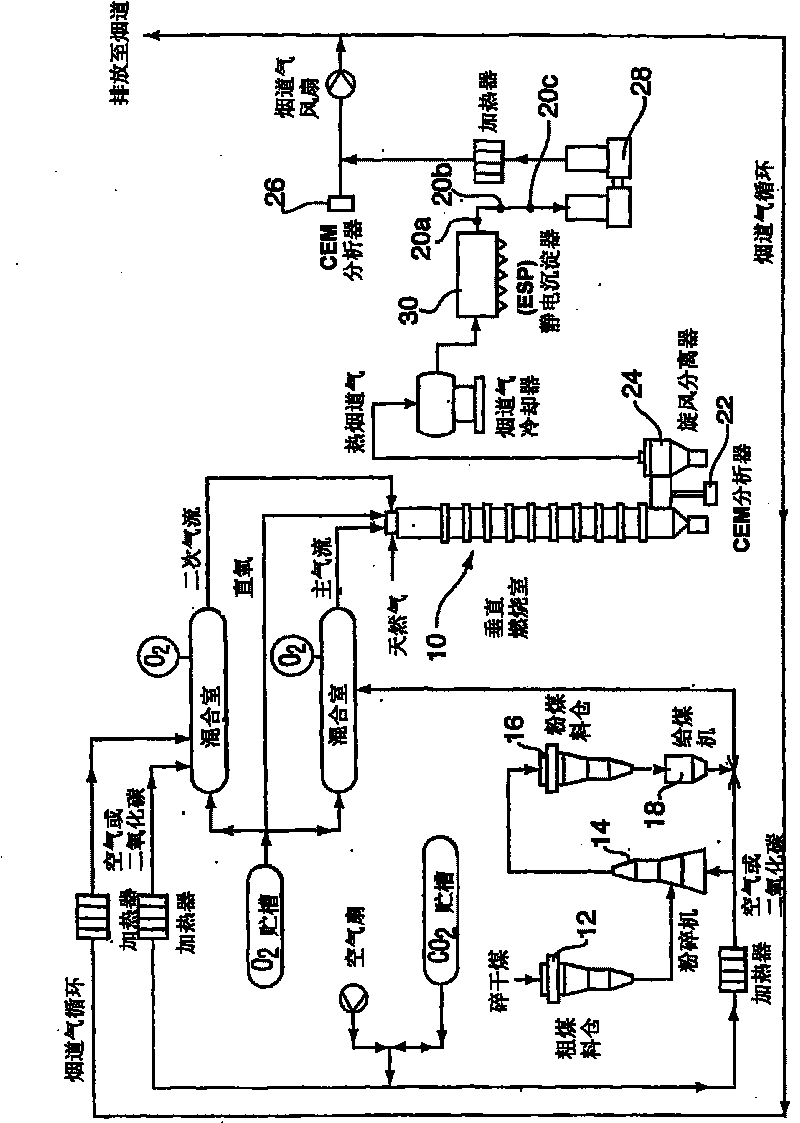
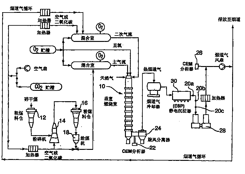
Image

Examples
Embodiment 1
[0059] Inject NaHCO at 6.6 kg / hr in all three ports 20a, 20b, 20c at 150°C for a short period (5 minutes) 3 , to observe it for SO 2 and NO x concentration effect. This was followed by a 1 hour continuous injection at port 20a after the short injection.
[0060] Sodium carbonate (Na 2 CO 3 ) aqueous solution was used as the wash solution and was added during the test to maintain the solution pH at approximately 7.
[0061] Table 3 summarizes the NaHCO 3 Average flue gas composition at combustor outlet and scrubber inlet before injection.
[0062]
[0063] Note that all concentrations are reported on a volumetric and dry basis.
[0064] Injection of sodium bicarbonate started at 0240 pm at port 20c (0.5 sec residence time) followed by ports 20b and 20a for 5 min each. Table 4 summarizes the flue gas composition at the time of injection.
[0065]
[0066] Table 5 shows the flue gas composition injected at port 20a for 1 hour.
[0067]
[0068] NaHCO 3 Injecti...
Embodiment 2
[0077] This test is performed by injecting NaHCO at three ports at a flow rate of 5.5kg / hr and an injection temperature of 150°C 3 conduct. The injection time at each port lasted 1 hour. Pre-filled wash solution: 1 kg of Na dissolved in 187 l of water 2 CO 3 , 29kg of Na 2 SO 4 and 19kg of Na 2 SO 3 . The pH of the prepared solution was about 10.6.
[0078] Start injecting NaHCO at port 20c 3 , and subsequently at ports 20b and 20a. Immediately after each injection is complete, the filter downstream of the injection port CEM system is changed to ensure an accurate readout of the flue gas composition.
[0079] Table 8 summarizes the NaHCO 3 Average flue gas composition at combustor outlet and scrubber inlet before injection.
[0080]
[0081] NaHCO injection started at 1237am at port 20c (0.5sec residence time) 3 , followed by 20a, each port lasted 60min. Table 9 summarizes the flue gas composition at the time of injection.
[0082]
[0083] As can be seen ...
Embodiment 3
[0085] In this example, NaHCO was performed at three ports at a flow rate of 7.7 kg / hr and an injection temperature of 150°C. 3 Injection. The injection time at each port lasted 1 hour. Pre-filled wash solution: 1 kg of Na dissolved in 187 l of water 2 CO 3 , 29kg of Na 2 SO 4 and 19kg of Na 2 SO 3 . The pH of the prepared solution was about 10.6.
[0086] Start injecting NaHCO at port 20c 3 , followed by 20a.
[0087] Table 10 shows the average injection temperature for each port.
[0088]
[0089] Table 11 summarizes the NaHCO 3 Average flue gas composition at combustor outlet and scrubber inlet before injection.
[0090]
[0091] Injection of sodium bicarbonate started at 1237 am at port C (0.5 sec dwell time) followed by port A for 60 min each.
[0092] Table 12 summarizes the flue gas composition at the time of injection.
[0093]
[0094] by injecting NaHCO at the 3 residence times of all trials 3 , NO and SO at the scrubber inlet 2 reduce simult...
PUM
 Abstract
Description
Claims
Application Information