Solid polymer electrolyte electrolytic bath

A solid polymer and electrolytic cell technology, applied in the field of electrolysis, can solve the problems of reduced catalyst utilization rate and unused catalyst, and achieve the effects of compact structure, simple processing and easy preparation

Active Publication Date: 2010-06-16
ENN SCI & TECH DEV
View PDF4 Cites 3 Cited by
  • Summary
  • Abstract
  • Description
  • Claims
  • Application Information

AI Technical Summary

Problems solved by technology

The patent does not mention the material of the separation layer. Processing the flow field on the separation layer has certain advantages and can save costs, but the direct contact between the current collector and the catalytic layer (or diffusion layer) on a large area will cause some catalysts to fail. Utilization, although this improves the electrolysis efficiency, but reduces the utilization rate of the catalyst

Method used


Image

  • Solid polymer electrolyte electrolytic bath
  • Solid polymer electrolyte electrolytic bath
  • Solid polymer electrolyte electrolytic bath

Examples


Embodiment 1

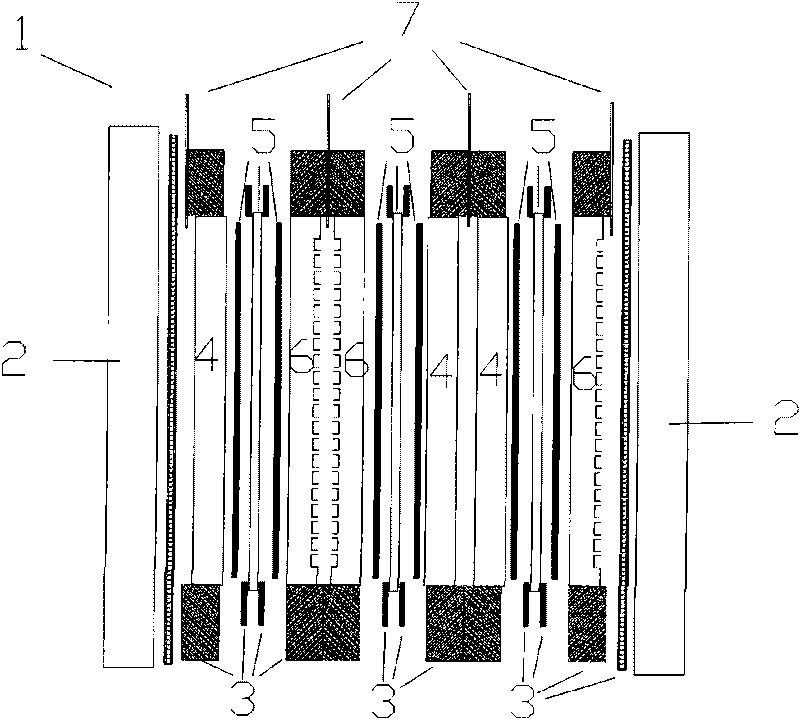
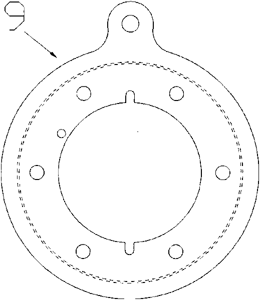
[0032] The SPE electrolytic cell structure of the present invention is mainly composed of two end plates [2], insulating material [3], cathode diffusion layer [4], MEA [5], anode integrated diffusion layer flow field [6], current collector [ 7] and so on. The anode diffusion layer is integrated with the flow field, and titanium powder is used as the base material, and the prepared mold is pressed under a certain temperature and pressure to obtain an integrated diffusion layer flow field. Two adjacent anodes or cathodes share a ring-shaped current collector, the current collector connected to the power supply cathode is in close contact with the two cathode diffusion layers [4], and the current collector connected to the power supply anode is in close contact with the two cathode diffusion layers [4]. The anode-integrated diffusion laminar flow field [6] is in close contact by means of pressure. MEA was prepared by spray method. The electrolytic cell is fastened with hexagon ...

Embodiment 2

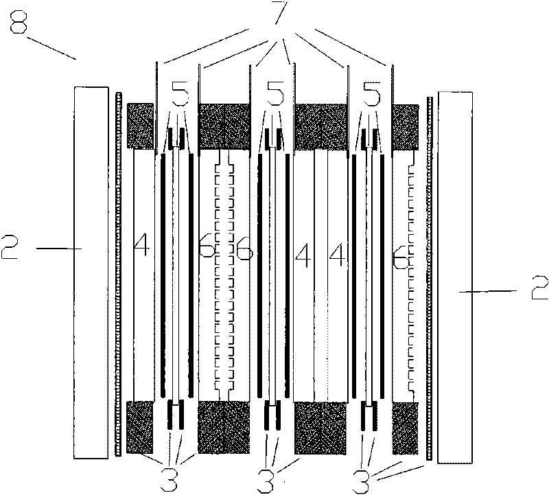
[0034] The SPE electrolytic cell structure of the present invention is mainly composed of two end plates [2], insulating material [3], cathode diffusion layer [4], MEA [5], anode integrated diffusion layer flow field [6], current collector [ 7] and so on. The anode diffusion layer is integrated with the flow field, and titanium powder is used as the base material, and the prepared mold is used for injection molding to obtain an integrated diffusion layer flow field. The current collector [7] connected with the power supply cathode is in close contact with the cathode diffusion layer [4] by means of pressing and sealing, and is sealed by insulating materials on both sides; the current collector connected with the power supply anode is connected with the anode diffusion layer and the flow field. The molds are in close contact with each other by pressing together to form the whole of the current collector and anode integrated diffusion layer flow field, and are sealed by insulati...

Embodiment 3

[0036] The SPE electrolytic cell structure of the first embodiment is adopted. A flow field with a certain groove-ridge ratio is processed on the anode diffusion layer by hot pressing with a die. Two adjacent anodes or cathodes share a ring-shaped current collector, and the ring-shaped current collector is placed between the two anode integrated diffusion layer flow fields [6] and connected by spot welding. Spot welding is used between the collector connected to the cathode of the power supply and the two cathode diffusion layers [4]. The MEA is prepared by chemical deposition method. The electrolytic cell is fastened with bolts.


PUM


Abstract

The invention discloses a solid polymer electrolyte electrolytic bath [1]. The electrolytic bath [1] mainly comprises an end plate [2], an insulating material [3], a cathode diffusion layer [4], a membrane electrode assembly (MEA) [5], an integrated anode diffusion layer flow field [6] and a collector [7]. The solid polymer electrolyte electrolytic bath is characterized in that: an anode diffusion layer is integrated with a flow field; the circular collector [7] contacts the cathode diffusion layer [4] and the integrated anode diffusion layer flow field [6] directly and tightly; and moreover, two adjacent anodes or cathodes share one feeding port or discharge outlet and share one collector. The solid polymer electrolyte electrolytic bath has the advantages of compact and simple structure, convenient processing, low cost, low electrolytic working voltage, high current density and electrolytic efficiency and long service life.

Description

technical field [0001] The invention relates to the field of electrolysis, in particular to a structure of an electrolytic cell using a solid polymer as an electrolyte and a preparation method thereof. Background technique [0002] Solid polymer electrolyte (Solid Polymer Electrolyte, SPE) electrolyzers have become the focus of research in various countries due to their compact structure, high current density, high electrolysis efficiency, safety and reliability, high gas purity, long service life, and large production capacity. The United States and Japan have an absolute advantage in this field, and they have developed hydrogen production capacity of 30 and 60Nm respectively. 3 / h SPE water electrolysis device. With the improvement of the electrolytic capacity of the electrolytic cell, its volume will become an important factor restricting its development. In addition, for SPE electrolyzers, high cost is the biggest obstacle to its development. On the one hand, the elect...

Claims


Application Information

Patent Timeline
Patent Type & Authority Applications(China)
IPC IPC(8): C25B9/00
Inventor 徐春保赵龙
Owner ENN SCI & TECH DEV
Why Eureka
Try Eureka