Axial flow fan

A technology of axial flow fan and shaft adjustment, which is applied in the direction of mechanical equipment, machine/engine, liquid fuel engine, etc. It can solve the problems of specification and quantity limitation, non-adjustable blade angle, and inability to adjust the blade working angle, etc., to achieve high strength and Toughness, the effect of avoiding fatigue fracture

Inactive Publication Date: 2010-06-16
NUOWENKE BLOWER FAN BEIJING
View PDF0 Cites 6 Cited by
  • Summary
  • Abstract
  • Description
  • Claims
  • Application Information

AI Technical Summary

Problems solved by technology

[0002] The blade base and the blade handle shaft of the existing mine axial flow main fan are generally connected by bolts, combined with figure 1 and figure 2 As shown, the blade base hole 3 for installing the blade 16 on the fan hub 17 is conical, and the corresponding blade base 1 is also conical, so the contact area between it and the disc of the petiole shaft must be relatively small.
The specifications and quantity of the bolt holes 2 provided on the blade base 1 are limited, so that the specification and quantity of the blade bolts used to fix the blade 16 and the petiole shaft disk are also limited, and cannot provide a large enough connection force, causing this type of In the actual use of the fan, the blade 16 and the shaft of the blade handle, that is, the connection strength between the blade 16 and the hub 17 is insufficient
At the same time, the existing blades 16 are all cast with aluminum alloy blades. Due to the defects of the casting process and the characteristics of the casting

Method used


Image

  • Axial flow fan
  • Axial flow fan
  • Axial flow fan

Examples


Embodiment Construction

[0018] The present invention will be further described in detail below in conjunction with the accompanying drawings and specific embodiments.

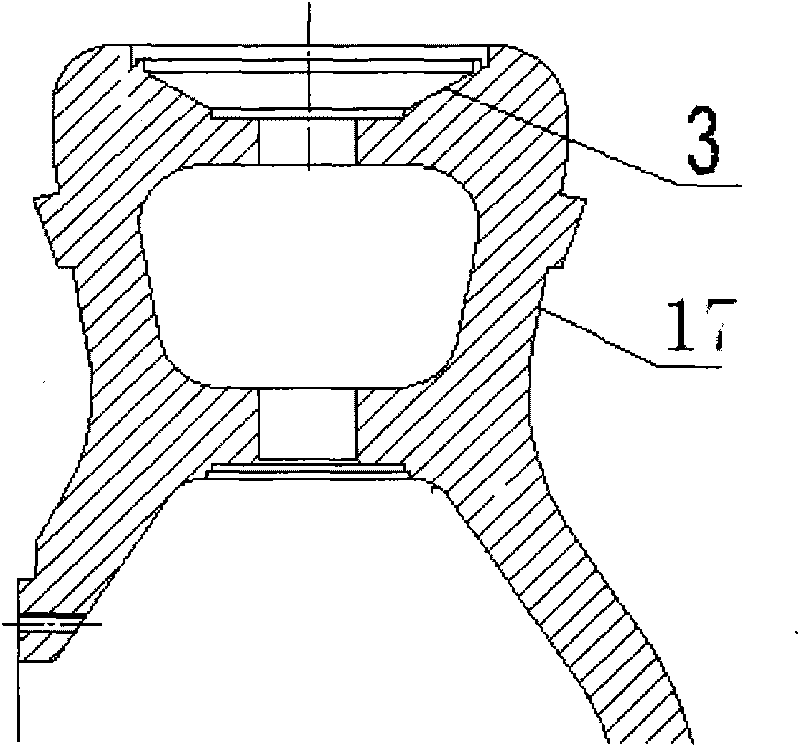
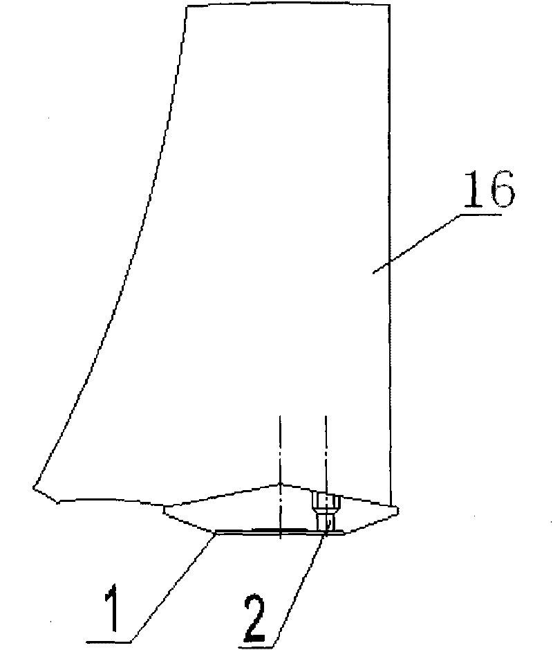
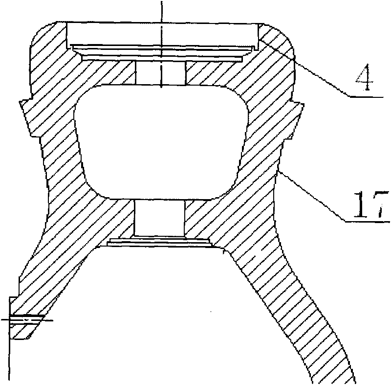
[0019] combine Figure 1 to Figure 4 As shown, the blade base hole 4 for installing the blade 16 on the hub 17 of the axial fan according to the present invention is an annular circular groove, and the blade base 5 is in the shape of a cylinder matching the annular groove. By changing the conical surface of the existing axial flow fan hub blade base hole 3 into a cylindrical surface, a larger space is reserved for the blade base 5, and the contact area of ​​the part where the blade base 5 is connected with the petiole shaft disk 15 is larger, and the blade base The diameter of the bolt hole 6 that offers on 5 is bigger, and quantity is also more, can install more blade bolts 13, and the diameter of blade bolt 13 is also bigger. Therefore, by improving the connection between the blade 16 and the petiole shaft 14, the strength of the c...


PUM


Abstract

The invention relates to an axial flow fan. A blade pedestal hole on a hub of the axial flow fan is an annular groove; a blade pedestal has a cylindrical shape which is matched with the annular groove; the area of a disk of a blade handle shaft is increased along with the increment of the area of the blade pedestal; a blade is a forged aluminum alloy blade; a blade bolt between the blade and the blade handle shaft is a large-size high-strength bolt; and the connection strength of the blade and the blade handle shaft is enhanced by changing the shapes of the blade pedestal hole for mounting the blade, the blade handle shaft and the blade pedestal, so that the operation of the fan is safer and more reliable. The invention also provides a blade angle adjusting device, which can adjust the operating angle of the blade once according to the machine needing to be stopped or at any time by a hydraulic system in the operational process. The axial flow fan effectively solves the problems that in the current mining axial flow main fan, the connection strength of the blade and the blade handle shaft is insufficient, the blade and the blade bolt are broken caused by fatigue and the like. At the same time, the axial flow fan can meet the requirement of digital mine construction on high-degree automatic control of the fan.

Description

technical field [0001] The invention relates to an axial-flow fan used for air intake and exhaust and gas circulation in industrial and mining enterprises, in particular to an axial-flow main fan with adjustable working angle of the fan blades for pumping and discharging underground waste gas from mines. Background technique [0002] The blade base and the blade handle shaft of the existing mine axial flow main fan are generally connected by bolts, combined with figure 1 and figure 2 As shown, the blade base hole 3 for installing the blade 16 on the fan hub 17 is conical, and the corresponding blade base 1 is also conical, so the contact area between it and the disc of the stalk shaft must be relatively small. The specifications and quantity of the bolt holes 2 provided on the blade base 1 are limited, so that the specification and quantity of the blade bolts used to fix the blade 16 and the petiole shaft disk are also limited, and cannot provide a large enough connection ...

Claims


Application Information

Patent Timeline
IPC IPC(8): F04D29/32F04D29/36F04D29/38
Inventor 李宏业
Owner NUOWENKE BLOWER FAN BEIJING
Why Eureka
Try Eureka