Oxygen-enriched fuel gas supply device and method for fuel gas injector

A gas supply and injector technology, which is applied in the testing of jet propulsion devices, rocket engine devices, gas turbine engines, etc., can solve the problems of difficult testing, difficult control and measurement, and small hydrogen flow, and reduce the difficulty of testing. effect on trial cost

Inactive Publication Date: 2010-06-16
BEIHANG UNIV
View PDF0 Cites 9 Cited by
  • Summary
  • Abstract
  • Description
  • Claims
  • Application Information

AI Technical Summary

Problems solved by technology

In a full-flow afterburning cycle engine, the mixing ratio of the oxygen-enriched pre-combustion chamber is high, and the hydrogen flow rate is small, especially in the single-nozzle gas nozzle test, the gas flow rate is small, and the hydrogen flow rate in the oxygen-enriched pre-chamber is extremely small, such as William M.Marshall , Sibtosh Pal, "Benchmark Wall Heat Flux Data for a GO2 / GH2 Single Element Combustor". AIAA 2005-3572 stated that the mixing ratio of the oxygen-enriched pre-combustion chamber is 165, and the hydrogen flow rate of the oxygen-enriched pre-combustion chamber is less than 0.5g / s. The flow rate in this document is used as a benchmark. If you want to study lower temperature gas nozzles, you must increase the mixing ratio, then the hydrogen will be smaller, and the control and measurement are difficult. Sophisticated test equipment and measurement equipment are required, and the cost is high. Pre-chamber design is difficult
At the same time, the oxygen-enriched pre-combustion chamber in this document is designed for the working condition of a single gas nozzle, with a fixed diameter and length, which is not suitable for experimental research when gas parameters need to be adjusted in a large range. When changing gas parameters, a new oxygen-enriched pre-combustion chamber needs to be replaced. Experiments are difficult and costly

Method used


Image

  • Oxygen-enriched fuel gas supply device and method for fuel gas injector
  • Oxygen-enriched fuel gas supply device and method for fuel gas injector
  • Oxygen-enriched fuel gas supply device and method for fuel gas injector

Examples


Embodiment Construction

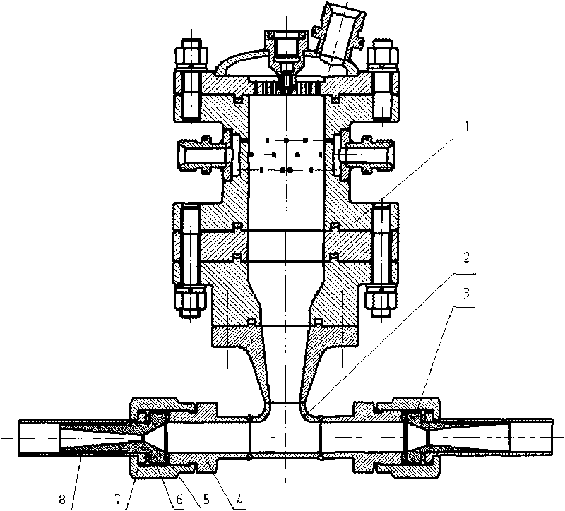
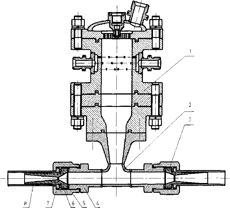
[0009] Further illustrate the present invention below in conjunction with accompanying drawing.

[0010] like figure 1 , the oxygen-enriched gas supply device includes: oxygen-enriched gas pre-combustion chamber 1, tee adapter 2, external sonic nozzle 3, nozzle 4, copper sealing gasket 5, oxygen-enriched gas inlet sonic nozzle 6, nut 7, pipe Connector 8. Oxygen-enriched pre-combustion chamber 1 can be designed under a large hydrogen flow rate, which is easy to control and measure. Through the three-way adapter 2, part of the oxygen-enriched gas passes through the oxygen-enriched gas inlet sonic nozzle 6 and enters the gas injector, and part of it passes through the outer sonic flow rate. The nozzle 3 opens into the atmosphere. The sonic nozzle is installed between the connecting nozzle 4 and the pipe fitting 8, and the pressure acting on the red copper sealing ring 5 by tightening the nut 7 realizes the sealing, and the sonic nozzle is easy to replace.

[0011] The specific...


PUM


Abstract

The invention relates to oxygen-enriched fuel gas device and method for a fuel gas injector and belongs to the field of the design of a propellant feed system of a rocket engine. The oxygen-enriched fuel gas device comprises an oxygen-enriched precombustion chamber (1), a tee adapter (2), an outfall sonic nozzle (3), a filler neck (4), a red copper sealing washer (5), an inlet sonic nozzle (6) of the oxygen-enriched fuel gas, a screw cap (7) and a pipe joint component (8). Part of the oxygen-enriched fuel gas enters the fuel gas injector through the tee adapter (2) by the inlet sonic nozzle (6) of the oxygen-enriched fuel gas, and the other part of the oxygen-enriched fuel gas is introduced into the atmosphere through the outfall sonic nozzle (3). The sonic nozzles are arranged between the filler neck (4) and the pipe joint component (8), and sealing is realized by the pressure of the tightening action of the screw cap (7) on the red copper sealing washer (5). By adopting a certain method to regulate the flow rate of the oxygen-enriched fuel gas and replace the inlet sonic nozzle (6) and the outfall sonic nozzle (3) of the oxygen-enriched fuel gas, the parameter requirement of the fuel gas injector is met. The design difficulty of the oxygen-enriched precombustion chamber can be lowered, and the cost and the workload of the test of the flow rate of the fuel gas injector are obviously lowered.

Description

【Technical field】 [0001] The invention relates to an oxygen-enriched gas supply device and method used in a gas injector test. 【Background technique】 [0002] The injector is one of the key components of the liquid rocket engine, and the performance of the injector directly affects the performance of the engine. [0003] The full-flow afterburning cycle system is a new type of rocket engine cycle system. It is the staged combustion technology with the highest combustion performance at present, and it is one of the important development directions of liquid rocket engine technology. In the technical research of full-flow afterburning cycle engine, gas-gas combustion is one of the key technologies. All flow of hydrogen and oxygen is combusted once in the pre-combustion chamber to drive the turbine and then enters the combustion chamber for the second combustion. Therefore, the nozzle of the thrust chamber of the full-flow afterburning cycle engine is a gas nozzle, which is di...

Claims


Application Information

Patent Timeline
IPC IPC(8): G01M15/14F02K9/44F02K9/52
Inventor 蔡国飙李茂高玉闪金平俞南嘉
Owner BEIHANG UNIV
Why Eureka
Try Eureka