Treatment process of garbage percolate

A landfill leachate and treatment process technology, which is applied in the field of landfill leachate treatment process, can solve the problems of large area occupied by facilities, small gas-liquid contact area, and inability to effectively solve ammonia nitrogen treatment, etc., so as to reduce the occupied area and reduce the The effect of small facility footprint

Inactive Publication Date: 2010-06-23
富康技术股份有限公司
View PDF1 Cites 11 Cited by
  • Summary
  • Abstract
  • Description
  • Claims
  • Application Information

AI Technical Summary

Problems solved by technology

However, the current separation membrane system is prone to membrane clogging due to various pollutants in the leachate. Once the membrane clogging occurs, the system cannot continue to operate.
[0016] 2) In addition, simply combining the traditional SBR process into the above process cannot effectively solve the problem of ammonia nitrogen treatment
In the biological treatment stage using the traditional SBR process, due to the influence of high concentration of ammonia nitrogen, the activity of nitrifying microorganisms is weakened, which has a certain inhibitory effect on the biological treatment system and is difficult to treat
Therefore, before the biological treatment, ammonia stripping, precipitation, ion exchange and other processes are generally set up separately to treat ammonia nitrogen, but in the above additional processes, processes such as sedimentation of the leachate in the sedimentation tank are required, so that additional facilities occupy Larger land area and longer processing time
In addition, the ammonia stripping method is usually carried out in an aeration tank or a stripping tower. The aeration tank has a low stripping efficiency due to the small gas-liquid contact area, while the stripping tower has a high efficiency in removing ammonia nitrogen, but there are operating costs High, the disadvantages of deamination tail gas is difficult to deal with, etc.

Method used


Image

  • Treatment process of garbage percolate
  • Treatment process of garbage percolate
  • Treatment process of garbage percolate

Examples


Embodiment Construction

[0034] Hereinafter, how to implement the technical solutions provided by the present invention will be further described in detail, and a non-limiting specific implementation manner of the present invention will be described in conjunction with the accompanying drawings.

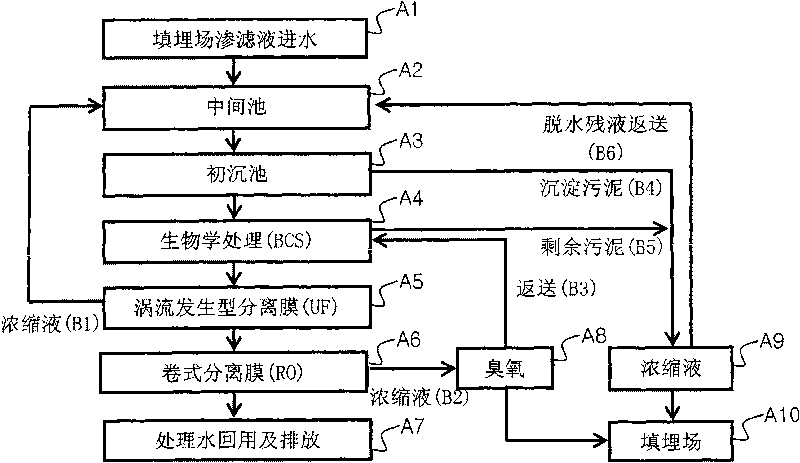
[0035] The vortex separation membrane device is used as the pretreatment device in the advanced treatment stage

[0036]The roll-type separation membrane used in the leachate treatment process of the present invention is a reverse osmosis membrane, and the treatment liquid needs to be pretreated before entering the reverse osmosis membrane for treatment, so as to remove solids. In the present invention, a vortex separation membrane device is used as a pretreatment device, wherein the membrane module is in the form of a flat membrane structure, and a vortex-generating rotating blade is placed between the membranes. In the prior art, there is a device that adopts a cross flow method to increase the flow velo...


PUM

PropertyMeasurementUnit
pore sizeaaaaaaaaaa
pore sizeaaaaaaaaaa

Abstract

The invention discloses a treatment process of garbage percolate, comprising: 1), a pre-treatment procedure, the garbage percolate is led into a middle tank and a primary settling tank for adjusting the water quality and the water quantity; 2) a biological treatment procedure, the treatment fluid which passes through the pretreatment procedure is treated through a SBR (Sequencing Batch Reactor Activated Sludge Process) biological treatment method; 3) an advanced treatment procedure, after the treated fluid passes through the biotical treatment procedure, the treated fluid enters a vortex-generating type separation membrane device for treating, and then enters a roll type separation membrane device for treating. Another aspect of the invention comprises adding bio-ceramic to the biological treatment procedure and the bio-ceramic is used as carrier. In the invention, the process combining the biological treatment and the physical treatment which utilizes the separation membrane is more stable, efficient; the input cost and the using and maintenance cost for the facility construction is further reduced.

Description

technical field [0001] The invention relates to a landfill leachate treatment process, in particular to purifying the landfill leachate for recycling or safe discharge. Background technique [0002] Landfill is a commonly used municipal solid waste disposal method. Due to compaction and microbial decomposition, the pollutants contained in the garbage will be dissolved with water, and form landfill leachate together with rainfall, runoff, etc. The leachate contains a large amount of refractory organic matter, nitrogen compounds, heavy metals and other substances harmful to microorganisms. Moreover, with the nature of garbage components, climate change and other factors, the water quality and water volume of leachate vary greatly, and the components gradually become complex, and change with the service life of the landfill. [0003] At present, landfill leachate treatment methods include sending it to urban sewage treatment plants for treatment, circulating spraying treatmen...

Claims


Application Information

Patent Timeline
Patent Type & Authority Applications(China)
IPC IPC(8): C02F9/14
Inventor 金樟圭金普显李龙王宇华
Owner 富康技术股份有限公司
Why Eureka
Try Eureka