
Dry-method coating machine

A coating machine and dry method technology, which is applied in the field of equipment for coating solid preparations with dry powder, can solve the problems of environmental pollution, high manufacturing cost, and low production efficiency, and achieve environmental friendliness, low manufacturing cost, and simple structure Effect

Inactive Publication Date: 2010-07-07
罗彦凤
View PDF8 Cites 17 Cited by
  • Summary
  • Abstract
  • Description
  • Claims
  • Application Information

AI Technical Summary

Problems solved by technology

[0003] At present, the equipment used to coat pharmaceutical solid preparations in the pharmaceutical industry is mainly a wet coating machine. After mixing the coating material with a solvent, it is attached to the surface of the solid preparation by spraying or printing through the coating machine, and then applied to the solid preparation. Drying and other treatments of the obtained solid preparation can form a uniform and smooth protective layer on the surface of the solid preparation. However, due to the characteristics of the wet coating process itself, if the solvent or water needs to be evaporated, the drying conditions are harsh, and waste liquid, solvent explosion-proof, etc., resulting in the disadvantages of energy consumption, long preparation cycle, environmental pollution, high production cost, etc.
[0004] In order to solve the problems existing in wet coating, people have studied the technology of directly using dry powder for coating, and manufactured dry coating equipment, mainly including heat-dry powder-coating equipment and electrostatic-dry powder-coating equipment. There are two types of coating equipment, which coat solid preparations in different ways, but both of these two equipments have disadvantages such as complex structure, high manufacturing cost, and low production efficiency, and are difficult to be used for large-scale coating processing

Method used


Image

  • Dry-method coating machine
  • Dry-method coating machine
  • Dry-method coating machine

Examples


Embodiment Construction

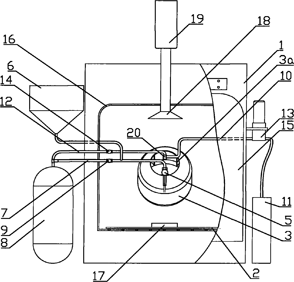
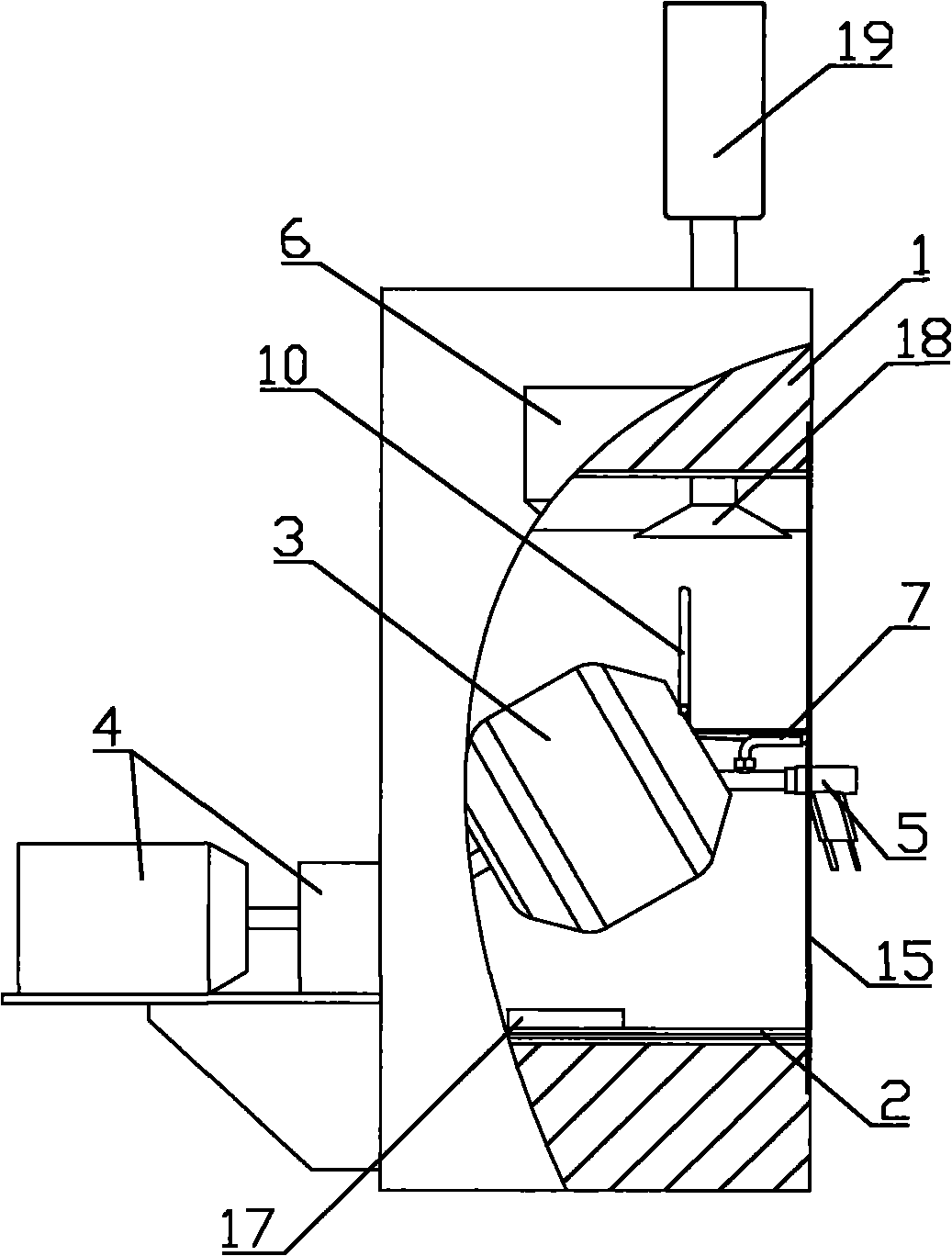
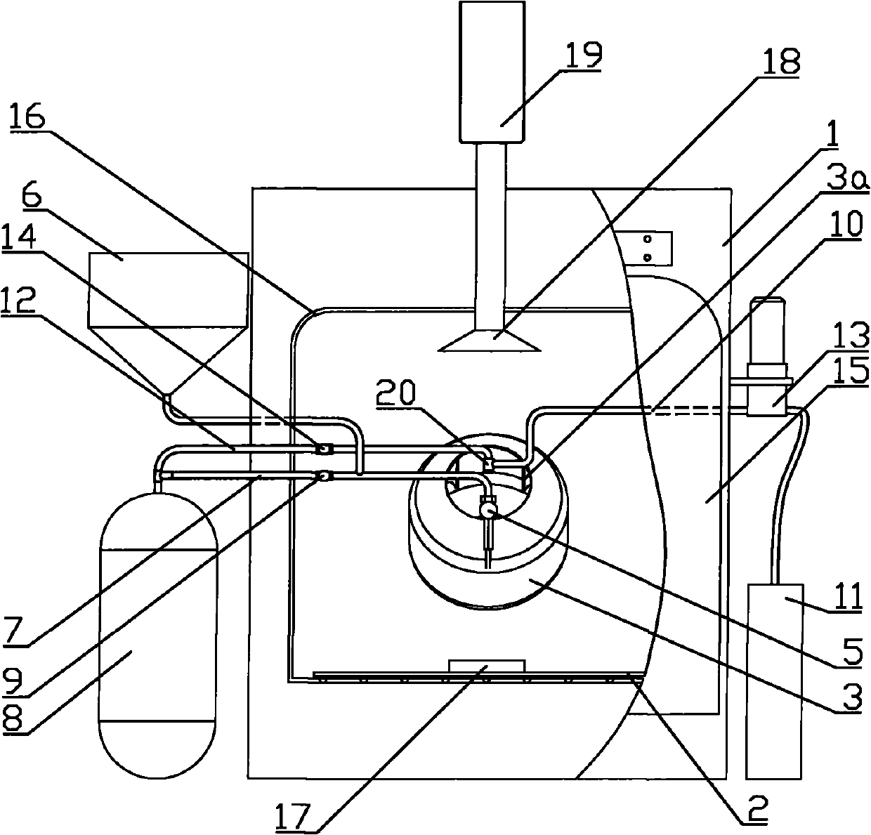
[0021] figure 1 It is a structural schematic diagram of the present invention, figure 2 for figure 1 As shown in the figure: the dry coating machine of this embodiment includes a box body, a coating device, a dry powder directional supply device and an auxiliary material supply device, and a heat source 2 is arranged at the inner bottom of the box body 1; The coating device includes a cylindrical coating pan 3 with an open end and a coating pan driving assembly 4. The coating pan 3 is arranged in the casing 1 in a manner that can rotate around its own axis, and the coating pan driving assembly 4 drives to cooperate with the coating. Pot 3; The dry powder directional supply device includes an electrostatic spray gun 5, a dry powder feed box 6, a dry powder conveying air pipe 7 and a high-pressure gas source 8, and the electrostatic spray gun of the present embodiment adopts a corona spray gun. A charged spray gun can also achieve the purpose of the present invention. One end...


PUM


Abstract

The invention discloses a dry-method coating machine which comprises a box body, a coating device, a dry powder directionally feeding device and an auxiliary material feeding device; when the dry-method coating machine is used, powder in a dry powder box enters into an electrostatic spray gun under the injection action of airflow in a dry powder conveying pipe and is electrified after treatment so as to form a potential difference with a grounded coating pan, and dry powder directionally enters into the coating pan under the driving of electric field force; meanwhile, an auxiliary material, such as a plasticizer, and the like is conveyed into an atomizer through a liquid conveying pipe under the action of a metering pump to form evenly-dispersed fog, the fog simultaneously or stepwise enters into the pan with the dry powder and contacts with a solid preparation in the pan, the dry powder is evenly adhered to the outer surface of the solid preparation with the rotation of the coating pan, and the dry powder can be rapidly softened to form a coating by regulating to appropriate ambient temperature so as to achieve the aim of highly-efficient coating; and in addition, the invention has simple structure, low manufacturing cost and environment protection and is suitable for industrialized coating production.

Description

technical field [0001] The invention relates to equipment for coating solid preparations with dry powder, in particular to a dry coating machine. Background technique [0002] Drug products mainly exist in two dosage forms, solid preparation and liquid preparation. In the actual production of solid preparation, due to the purpose of masking the smell of the drug, preventing moisture, avoiding light, controlling the release site and release rate of the drug during use, it is necessary to use a specific The material is coated with it. [0003] At present, the equipment used to coat pharmaceutical solid preparations in the pharmaceutical industry is mainly a wet coating machine. After mixing the coating material with a solvent, it is attached to the surface of the solid preparation by spraying or printing through the coating machine, and then applied to the solid preparation. Drying and other treatments of the obtained solid preparation can form a uniform and smooth protective...

Claims


Application Information

Patent Timeline
Patent Type & Authority Applications(China)
IPC IPC(8): A61J3/06
Inventor 罗彦凤
Owner 罗彦凤
Learn More