Complex vacuum deposition device

A technology of equipment and vacuum chamber, applied in the field of composite vacuum deposition equipment, can solve the problems of not realizing the optimal distribution of reaction gas, poisoning of magnetron sputtering source, etc., and achieve the effect of optimizing working range and reducing coating defects

Inactive Publication Date: 2010-07-07
CHINA UNIV OF GEOSCIENCES (BEIJING)
View PDF0 Cites 16 Cited by
  • Summary
  • Abstract
  • Description
  • Claims
  • Application Information

AI Technical Summary

Problems solved by technology

[0005] At present, the composite coating equipment that has been developed to integrate magnetron sputtering source, cathodic arc evaporation source and auxiliary ion source has not achieved the optimal distribution of reaction gas. The

Method used


Image

  • Complex vacuum deposition device
  • Complex vacuum deposition device

Examples


Example Embodiment

[0020] Implementation mode:

[0021] The patent of the present invention will be described in detail below in conjunction with the accompanying drawings.

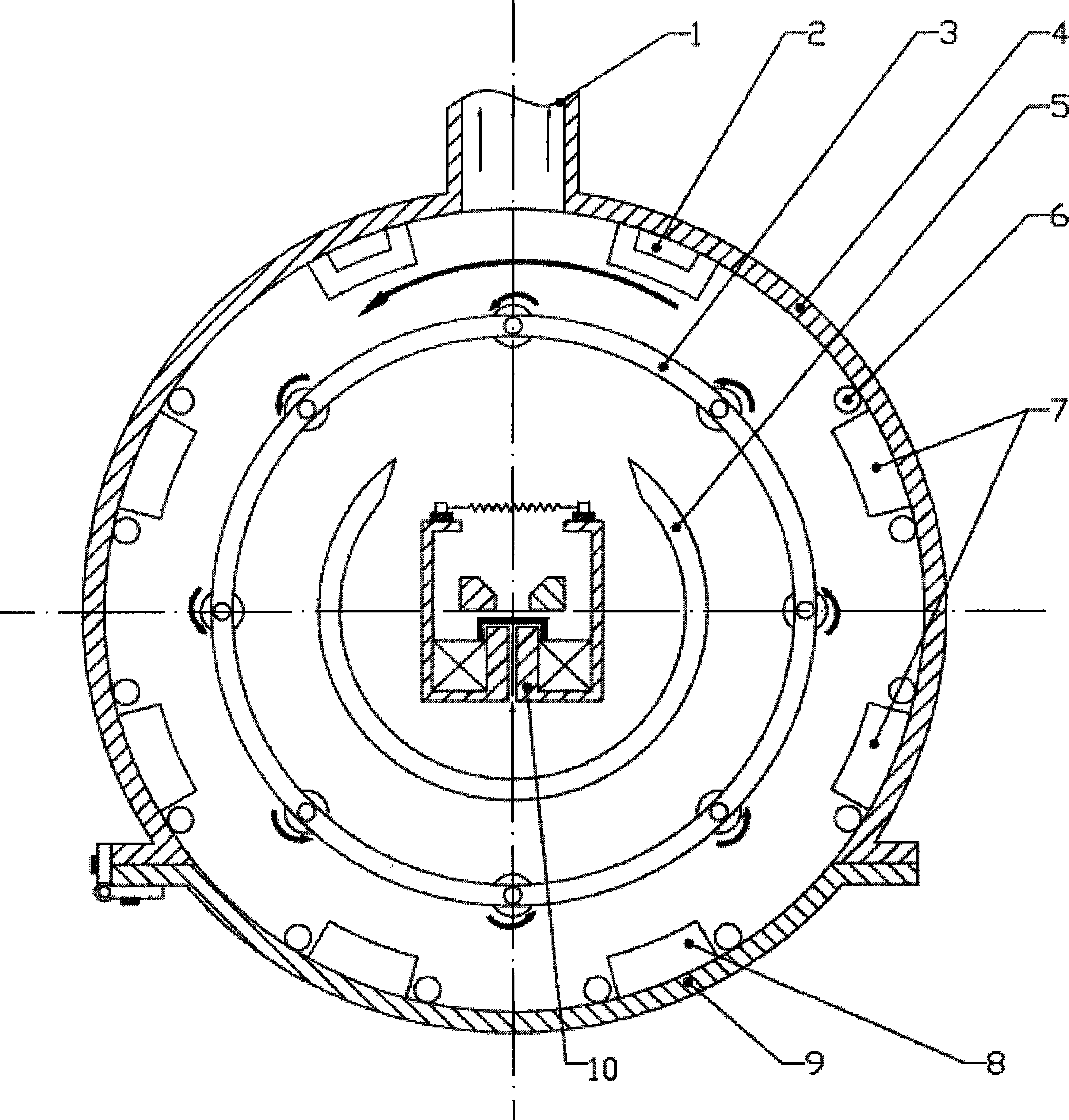
[0022] A new type of composite vacuum deposition equipment, which mainly consists of coating chamber 4, cathodic arc evaporation source 2, intermediate frequency magnetron sputtering source 7, DC magnetron sputtering source 8, gas ion source 10, working gas inlet pipe 6, workpiece Frame 3 and vacuum acquisition system, vacuum measurement system, air intake system, power supply and control system. The suction port 1 is installed on the back side of the vacuum chamber and connected with the vacuum obtaining system. The cathodic arc evaporation source 2 is installed on the vacuum chamber wall on both sides of the suction port 1, the intermediate frequency magnetron sputtering source 7 is installed on the vacuum chamber wall in the middle of the left and right sides, and the DC magnetron sputtering source 8 is installed far away O...


PUM


Abstract

The invention relates to a complex vacuum deposition device which consists of a vacuum chamber 4, a cathodic arc evaporation source 2, a middle frequency magnetron sputtering source 7, a direct current magnetron sputtering source 8, a gas ion source 10, a workpiece rest 3 and the like; a gas extraction port 1 is formed at the back of the vacuum chamber 4, the cathodic arc evaporation source 2 is mounted on the vacuum chamber wall which is near to the gas extraction port 1, the middle frequency magnetron sputtering source 7 is mounted on the vacuum chamber wall in the middle position of the two sides of the vacuum chamber 4, and the direct current magnetron sputtering source 8 is mounted on a front door 9 of the vacuum chamber; the gas ion source 10 is mounted in the central position of the vacuum chamber 4, reaction gas is introduced into the gas ion source 10, an ion beam is sprayed to the direction of the gas extraction port 1, and baffle plates 5 of the gas ion source are arranged at the back part and on the side surface of the ion source 10; and working gas is introduced into the vacuum chamber 4 through a working gas inlet pipeline 6 which is in the vicinity of the middle frequency magnetron sputtering source 7 and the direct current magnetron sputtering source 8. The arrangement can form the ideal reaction gas concentration distribution in the vacuum chamber, thereby fully playing the advantages of various film-forming sources and significantly inhibiting the defects of thin films.

Description

Technical field: [0001] The patent of this invention relates to a new type of composite vacuum deposition equipment, which is used for surface modification of materials and deposition of functional thin films. Background technique: [0002] Magnetron sputtering and cathodic arc ion plating have been widely used in wear-resistant parts, optical films, molds, decoration, microelectronics and other fields. Compound materials play an important role in coating materials prepared by magnetron sputtering and vacuum cathodic arc ion plating. [0003] Magnetron sputtering can prepare compound coatings by sputtering compound targets, and can also prepare compound coatings by reactive magnetron sputtering of metal or alloy targets. The former generally requires the use of radio frequency sputtering power supply and high-cost compound targets, and the deposition rate is low; the targets of reactive sputtering are easy to obtain and suitable for large-area uniform deposition, and have b...

Claims


Application Information

Patent Timeline
IPC IPC(8): C23C14/35C23C14/32
Inventor 付志强王成彪张伟岳文彭志坚于翔
Owner CHINA UNIV OF GEOSCIENCES (BEIJING)
Why Eureka
Try Eureka