Blast-furnace slag processing system

A treatment system and technology for blast furnace slag, which is applied in the field of metallurgical ironmaking equipment, can solve the problems of high energy consumption for long-distance transportation of slag-water mixture, difficulties in maintenance of bottom filter tanks, large floor area of ​​advection tanks, etc., and achieve equipment and facilities Simplicity, improved system reliability, and high slag flushing rate

Active Publication Date: 2011-11-16
CISDI ENG CO LTD
View PDF0 Cites 0 Cited by
  • Summary
  • Abstract
  • Description
  • Claims
  • Application Information

AI Technical Summary

Problems solved by technology

The disadvantages of this method are: the advection tank occupies a large area, the layout of the general plan is difficult, the long-distance transportation of the slag-water mixture consumes a lot of energy, the finished product slag captured in the advection tank contains high free water, and dripping occurs during the process of transporting the slag. serious, environmental pollution
The disadvantage of this method is: the switch valve under the bottom filter group is soaked in slag water, the slag water is highly corrosive, and the valve is easily damaged. When filtering, slag grasping, and maintenance of the filter tank, a large amount of back-irrigation water will be generated due to lax valves, resulting in bottom filtration. It is difficult to overhaul and maintain the pool, and the bottom filter pool is located very deep below the floor surface, and the excavation volume of earthwork is large

Method used


Image

  • Blast-furnace slag processing system
  • Blast-furnace slag processing system
  • Blast-furnace slag processing system

Examples


Embodiment Construction

[0030] Attached below Figure 1~4 The specific embodiment of the present invention is described in further detail:

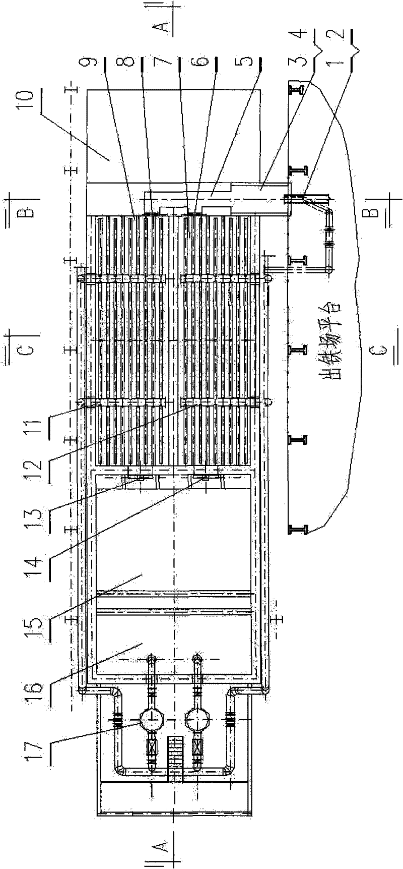
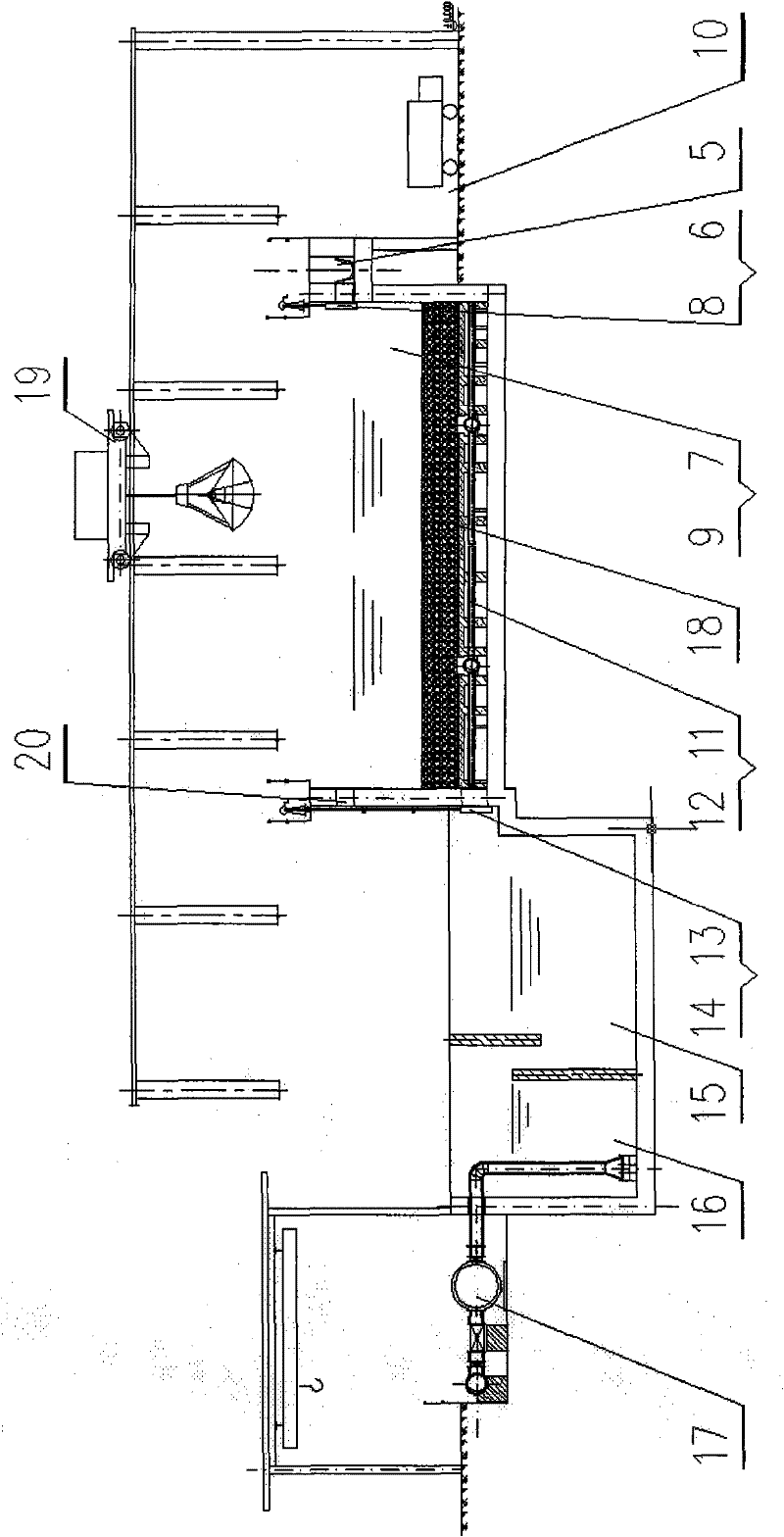
[0031] In the present invention, in the narrow and long free space on the side of the casthouse, the bottom filter group is arranged close to the casthouse and above the ground level, and an advection pool and a circulation pool are arranged in series behind the bottom filter group, and the advection pool and circulating pools are located below ground level.

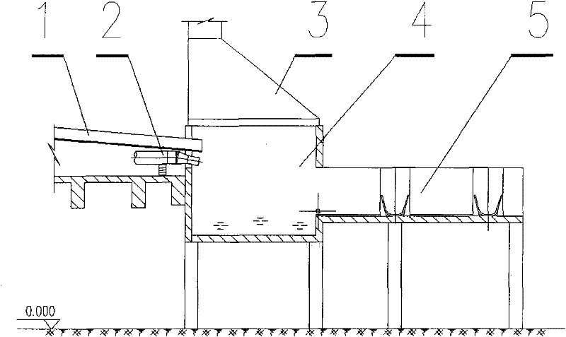
[0032] The slag ditch 1 and the punching box 2 of the blast furnace slag treatment system are connected with the slag flushing tank 4, the slag flushing tank 4 is connected with the steam chimney 3, and the water slag ditch 5, and the water slag ditch 5 passes through the slurry valve 6, the slurry valve 8, They are respectively connected with the bottom filter tanks 7 and 9; the bottom side of the bottom filter tanks 7 and 9 are provided with outlet holes, and are connected with the advection tank 15 thr...


PUM


Abstract

The invention belongs to the technical field of metallurgical iron-making devices, and specifically relates to a blast-furnace slag processing system. The blast-furnace slag processing system mainly comprises a bottom filter chamber group, a horizontal flow chamber and a circulating water chamber, wherein the bottom filter chamber group is arranged closely adjacent to a casting house in the long and narrow spare space at the casting house side and is positioned above the ground level, the horizontal flow chamber and the circulating water chamber connected in series are arranged behind the bottom filter chamber group, and the horizontal flow chamber and the circulating water chamber are positioned under the ground level. The invention is characterized in that the overall system is arrangedclosely adjacent to the casting house side, thereby avoiding the long distance conveyance of the slag-water slurry; and the bottom filter chamber is positioned above the ground level, thereby fully making use of the space in the horizontal plane and the vertical plane at the casting house side. The invention has the advantages of small occupied area, simple equipment and facility, low construction investment, low operating cost, convenient operation and maintenance and environmental friendliness, and achieves the effects of environmental protection, high efficiency and energy saving. The invention can be widely used in the blast-furnace slag processing system, and can also be used in other slag-flushing processing systems.

Description

technical field [0001] The invention belongs to the technical field of metallurgical ironmaking equipment, and in particular relates to a blast furnace slag processing system. Background technique [0002] At present, the treatment of blast furnace slag by ironmaking enterprises at home and abroad is generally divided into two categories: mechanical equipment method and conventional water flushing method (slag pool method). Mechanical equipment method includes INBA method, cage stirring method, wheel method and other systems; conventional flushing method (slag pool method) includes advection method and bottom filtration method and other systems. [0003] The mechanical equipment method has the advantages of mechanization and high degree of automation, but most of them are foreign patented technologies, and the patent fee and equipment introduction are expensive, and the investment cost and operation cost are high. [0004] The process flow of the advection method in the con...

Claims


Application Information

Patent Timeline
Patent Type & Authority Patents(China)
IPC IPC(8): C21B3/06
CPCY02W30/50
Inventor 李恩健
Owner CISDI ENG CO LTD
Why Eureka
Try Eureka