Configurable phase discriminator for time-delay locking ring

A delay-locked loop and phase detector technology, applied in the automatic control of power, electrical components, etc., can solve problems such as clock cycle and cycle jitter, limit the performance of the phase detector, and incorrect phase difference information, etc., to achieve the realization principle Simplicity, improved jitter performance, effects for reusability

Active Publication Date: 2010-07-28
BEIJING MXTRONICS CORP +1
View PDF0 Cites 27 Cited by
  • Summary
  • Abstract
  • Description
  • Claims
  • Application Information

AI Technical Summary

Problems solved by technology

In addition, for non-ideal phase detectors, incorrect phase difference information may cause jitter between clock cycles in the output signal of the phase-locked loop circuit
The digital phase detector may exhibit low gain or zero gain in a region near zero phase difference. This low gain region is usually called the dead zone. The existence of the dead zone problem greatly limits the performance of the phase detector. Early The designer solves the phase detection dead zone problem by intentionally introducing a phase difference so that the phase detector does not work in the area near zero phase difference. Although this method is also effective, it will generate noise at the output of the phase locked loop frequency synthesizer

Method used


Image

  • Configurable phase discriminator for time-delay locking ring
  • Configurable phase discriminator for time-delay locking ring
  • Configurable phase discriminator for time-delay locking ring

Examples


Embodiment Construction

[0028] Below in conjunction with accompanying drawing and specific embodiment the present invention is described in further detail:

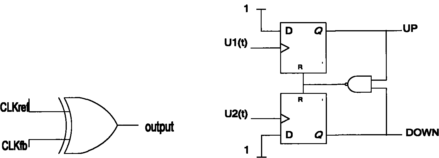
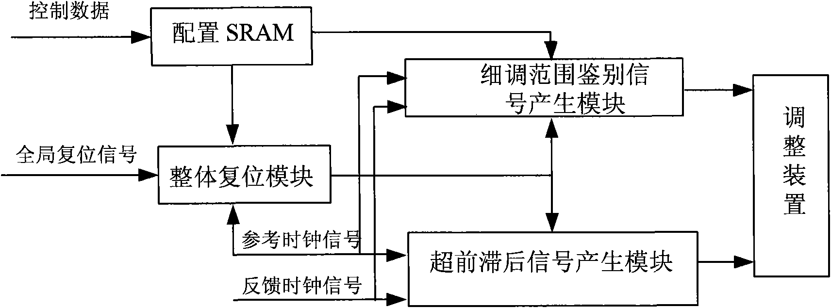
[0029] Such as figure 2 Shown is a schematic structural diagram of the configurable phase detector of the present invention, which includes a configuration SRAM, an overall reset module, a lead-lag signal generation module and a fine-tuning range discrimination signal generation module.

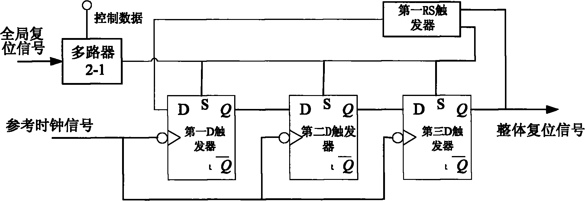
[0030] Configure the SRAM to store and control the data flow of the configurable performance index of the configurable phase detector. The configurable characteristics of the configurable phase detector of the present invention include whether the global reset signal input to the overall reset module is effective at high level or low level, And the pulse width of the pulse generating circuit in the fine-tuning range discrimination signal generating module, the pulse width directly represents the phase difference between the reference clock signal and the feedb...


PUM


Abstract

The invention relates to a configurable phase discriminator for a time-delay locking ring, which comprises a configurable SRAM, an integral resetting module, an advanced-lagged signal generating module and a fine adjusting range identification signal generating module. Data in the embedded configurable SRAM is changed and different phase discriminating precisions are set according to different application requirements, so as to realize the controllability of fine and rough adjusting; meanwhile, as the embedded configurable SRAM controls different starting moments of fine adjusting, the structure of hardware does not need to be changed in the using process and the locking time of a loop circuit can be adjusted only by changing a code stream in the SRAM according to the requirements. In addition, the advanced-lagged signal generating module which is composed of two D triggers and three RS triggers is used for sampling and outputting two input clock signals and judging whether the two input clock signals are advanced or lagged; the fine adjusting range identification signal generating module which is composed of a nand gate and two pulse generating circuits is used not only for judging whether the phase difference of the two clocks reaches the set fine adjusting range, but also for controlling the starting time of fine adjusting by controlling the pulse generating width.

Description

technical field [0001] The present invention relates to a phase detector circuit, in particular to a configurable phase detector for a delay locked loop. Background technique [0002] With the increase of FPGA size and density, the design process is advancing to deep submicron or nanometer, the distribution quality of the clock on the chip becomes more and more important, and the clock skew and clock delay become one of the key factors affecting the performance of the chip. In large-scale, high-speed field integration design, the number of branches on the clock network is increasing. Using the traditional clock tree method, the size of the buffer is used in the middle of each branch to adjust the clock delay on each branch to reduce the clock delay. Skew and clock delays become very difficult. Phase-locked loop technology has opened up a new direction for the problems of clock management in FPGA circuits. Phase-locked loop technology includes delay-locked loop DLL (Delay-Lo...

Claims


Application Information

Patent Timeline
Patent Type & Authority Applications(China)
IPC IPC(8): H03L7/08
Inventor 王慜陈雷张彦龙李学武刘增荣禹放斌
Owner BEIJING MXTRONICS CORP
Why Eureka
Try Eureka