Manufacturing method of solder ring component for magnetron cathode assembly

A magnetron cathode and manufacturing method technology, applied in cold cathode manufacturing, discharge tube/lamp manufacturing, electrode system manufacturing, etc., can solve the problems of complex process, poor operability, high cost, etc., achieve simplified preparation process, and improve finished product The effect of improving production efficiency and yield

Inactive Publication Date: 2012-05-30
XIAMEN HONGLU TUNGSTEN MOLYBDENUM IND CO LTD
View PDF0 Cites 0 Cited by
  • Summary
  • Abstract
  • Description
  • Claims
  • Application Information

AI Technical Summary

Problems solved by technology

[0009] Using the powder metallurgy molding method to produce the solder ring parts for the magnetron cathode assembly has disadvantages such as complicated procedures, high cost, low efficiency, and poor operability.

Method used


Image

  • Manufacturing method of solder ring component for magnetron cathode assembly
  • Manufacturing method of solder ring component for magnetron cathode assembly
  • Manufacturing method of solder ring component for magnetron cathode assembly

Examples


example 1

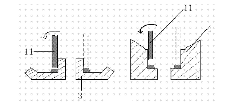
[0028] An appropriate amount of Mo powder and Ru powder were ground in a high-energy ball mill for 25 hours to obtain evenly distributed solder powder. Mix the solder powder with a small amount of organic matter, such as terpineol and ethyl cellulose, to obtain a solder paste with certain fluidity. Automatic grouting device and image 3 The movement form of the needle relative to the molybdenum end cap shown in , accurately, uniformly and efficiently coats the solder paste on the groove of the molybdenum end cap, and forms a regular ring shape. Then, degrease and sinter the molybdenum end cap coated with solder paste in a hydrogen atmosphere furnace. The heating rate in the range of 150-550°C is 1.5°C / min, and the maximum sintering temperature is 1650°C, finally forming a solder ring part in the molybdenum end cap.

example 2

[0030] An appropriate amount of Mo powder, Ru powder and Ni powder were ground in a high-energy ball mill for 15 hours to obtain evenly distributed solder powder. Mix the solder powder with a small amount of organic matter, such as rosin, ethyl cellulose and paraffin wax emulsion, to obtain a solder paste with certain fluidity. Automatic grouting device and Figure 5 The movement form of the needle relative to the molybdenum end cap shown in , accurately, uniformly and efficiently coats the solder paste on the groove of the molybdenum end cap, and forms a regular ring shape. Then, the molybdenum end cap coated with solder paste is degreased in a furnace with a nitrogen atmosphere, and sintered in a furnace with a hydrogen atmosphere. The heating rate is 1°C / min in the range of 150-550°C, and the highest sintering temperature is 1450°C, finally forming a solder ring part in the molybdenum end cap.

example 3

[0032] An appropriate amount of Mo powder, Fe powder and Ni powder were ground in a roller mill for 10 h to obtain evenly distributed solder powder. Mix the solder powder with a small amount of organic matter, such as rosin, hydrogenated castor oil and paraffin emulsion, to obtain a solder paste with certain fluidity. Automatic grouting device and Figure 7 The movement form of the needle relative to the molybdenum end cap shown in , accurately, uniformly and efficiently coats the solder paste on the groove of the molybdenum end cap, and forms a regular ring shape. Then, the molybdenum end cap coated with solder paste is degreased in a furnace with an argon atmosphere, and sintered in a furnace with a hydrogen atmosphere. The heating rate is 2°C / min in the range of 150-550°C, and the maximum sintering temperature is 1100°C, finally forming a solder ring part in the molybdenum end cap.


PUM


Abstract

The invention provides a novel manufacturing method of a solder ring component for a magnetron cathode assembly. The manufacturing method comprises the following steps of: grinding raw powder for 2-30h to obtain solder powder, evenly mixing the solder powder with a small amount of volatile organic matters with heating energy being decomposed completely to obtain solder slurry with a certain mobility, coating the solder slurry at a molybdenum end cap groove by utilizing an automatic slurry coating device and forming a regular ring shape, putting an molybdenum end cap after coating the solder slurry into a stove with protective gas, respectively degreasing at a temperature of 150-550 DEG C and sintering at a temperature of 800-1700 DEG C, and forming the solder ring component in the molybdenum end cap. The invention has the advantages of greatly simplifying the current production process of a solder ring, realizing the automatic and continuous production, greatly reducing the cost and improving the product performance and the production efficiency.

Description

technical field [0001] The invention relates to a new method for manufacturing a solder ring part for a magnetron cathode assembly. Background technique [0002] The magnetron is the core component of high-frequency heating systems such as microwave ovens, and the cathode assembly is the heart of the magnetron, which is mainly used for directional emission of electrons. Magnetron cathode components such as figure 1 As shown, its main composition is as follows: the upper end and the lower end of the magnetron coil 1 are respectively connected with the upper molybdenum end cap 3 and the lower molybdenum end cap 4 through solder 2; the central pole 5 is fixedly connected with the upper molybdenum end cap 3; the side poles 6 is fixedly connected with the lower molybdenum end cap 4. [0003] The assembly process of the above-mentioned magnetron cathode assembly is as follows: first put the solder ring 2 into the grooves of the upper molybdenum end cap 3 and the lower molybdenum...

Claims


Application Information

Patent Timeline
Patent Type & Authority Patents(China)
IPC IPC(8): B22F3/10H01J9/02
Inventor 罗梦文欧阳明亮石涛赖亚洲于洋庄志刚
Owner XIAMEN HONGLU TUNGSTEN MOLYBDENUM IND CO LTD
Why Eureka
Try Eureka