Pure medium-low temperature waste heat generating system in cement kiln

A low-temperature waste heat and power generation system technology, applied in cement production, preheating, waste heat treatment, etc., can solve the problem of reduced power generation of steam turbine generators, low temperature and pressure parameters of thermal systems, and insufficient use of high-temperature hot air from clinker coolers and other issues, to achieve the effect of increasing power generation capacity, improving power generation capacity, and increasing temperature

Inactive Publication Date: 2010-08-04
LUOYANG CEMENT ENG DESIGN & RES INST
View PDF6 Cites 19 Cited by
  • Summary
  • Abstract
  • Description
  • Claims
  • Application Information

AI Technical Summary

Problems solved by technology

[0004] 1. The kiln head clinker cooler is from the feed end (hot end) of the cooler to the discharge end (cold end). Under the condition of not affecting the heat consumption of cement kiln clinker and the production of cement kiln, the cooler can discharge The exhaust gas temperature is 600°C from the hot end and gradually decreases to 55°C at the cold material end in a linear relationship. If the waste gas is extracted from the middle after the waste gas from the hot end and cold end of the clinker cooler is mixed, the heat of the exhaust gas will not be adjusted according to its temperature. High and low cascade utilization
In this way, the AQC furnace can only produce low-pressure and low-temperature steam, and the temperature and pressure parameters of the thermal system are low, and the high-temperature hot air in the cli

Method used


Image

  • Pure medium-low temperature waste heat generating system in cement kiln
  • Pure medium-low temperature waste heat generating system in cement kiln

Examples


Embodiment 1

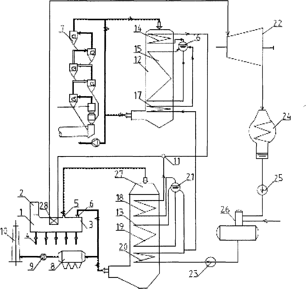
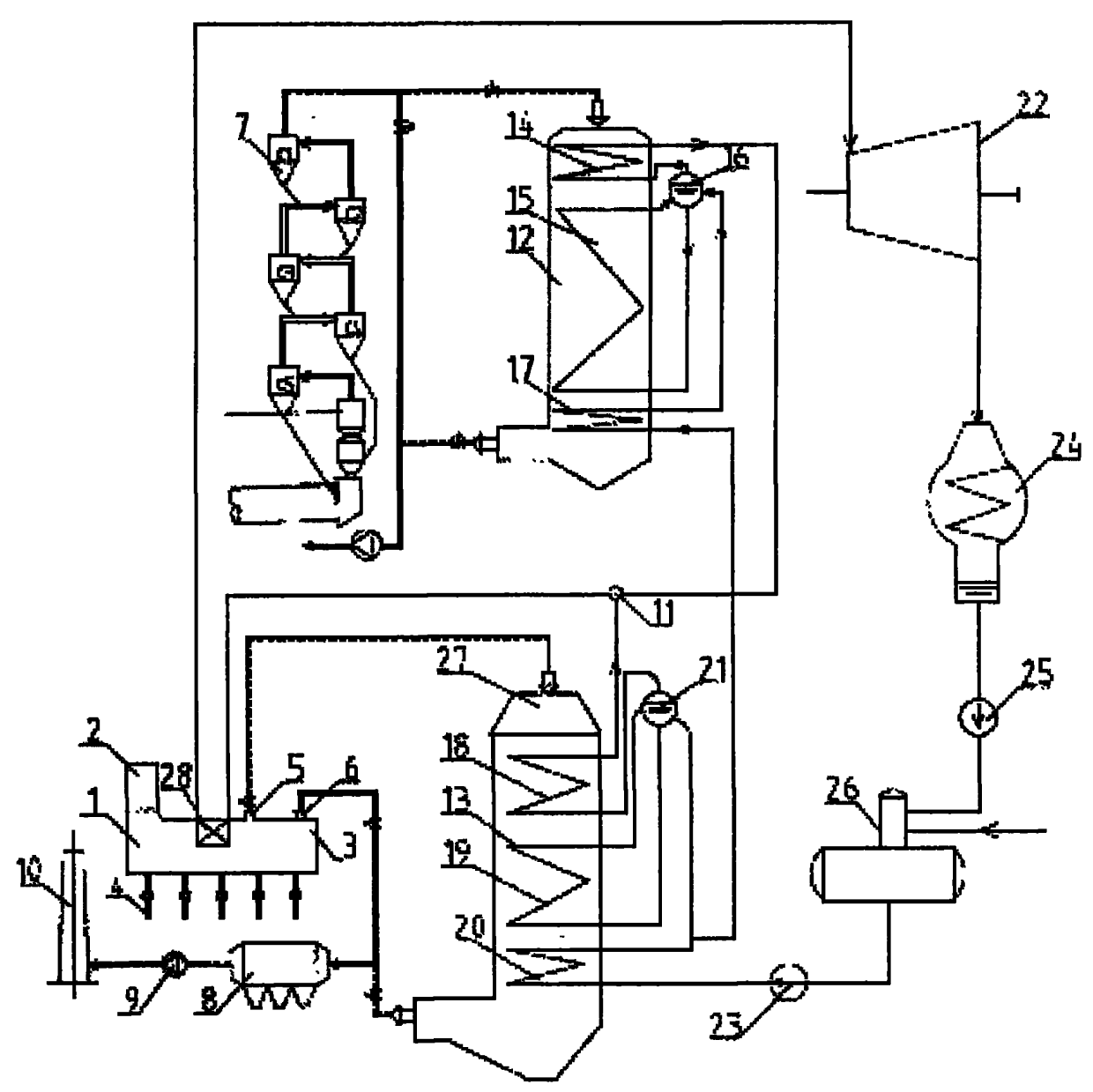
[0022] like figure 1 As shown, the present invention includes clinker cooler 1, kiln tail preheater 7, AQC furnace 13, SP furnace 12, AQC furnace steam drum 21, SP furnace steam drum 16, steam turbine 22, boiler feed water pump 23, dust collector 8 , fan II9, chimney 10, the clinker cooler 1 is provided with a feed end 2 and a discharge end 3, the clinker cooler 1 is provided with a public high-temperature superheater 28 near the feed end 2, and the middle part is provided with a central air outlet 5. Near the discharge end 3, there is a tail exhaust port 6, a fan I4, and a set of fans are provided on both sides of the lower part of the clinker cooler 1. The middle exhaust port 5 is connected to the waste gas inlet of the AQC furnace 13, and the tail exhaust port 6 passes through the dust collector. 8. The fan II9 is ​​connected to the chimney 10, the outlet of the kiln tail preheater 7 is connected to the waste gas inlet of the SP furnace 12, and the SP furnace 12 is equipped...


PUM


Abstract

The invention relates to a pure medium-low temperature waste heat generating system in a cement kiln. The invention is characterized in that an AQC boiler is arranged at the kiln head to generate low-temperature low-pressure steam; an SP boiler is arranged at the kiln tail to generate low-temperature low-pressure steam; the low-temperature low-pressure steam generated by the two waste heat boilers are mixed by a steam distributor and then goes into a common high-temperature superheater arranged in the front end of a grate cooler at the kiln head, the low-temperature low-pressure steam generated by the AQC boiler and the SP boiler is superheated into high-temperature high-pressure steam and then goes into a condensing steam turbine, the dead steam after the action of the steam turbine goes into a condenser, condensation water goes into a vacuum deaerator through a condensation water pump and a pipeline to deoxidize, and the deoxidized water goes into the AQC boiler and the SP boiler through a boiler feed pump. By reasonably using the waste steam temperature in the cement kiln and carrying out the cascading use of the waste steam heat based on the temperature, the invention reduces or avoids the entropy phenomena, and enables the temperature of the superheated steam at the inlet of the steam turbine to be raised, thereby realizing the pure medium-low temperature waste heat generating system in the cement kiln, of which the generating capacity is improved.

Description

technical field [0001] The invention relates to a cement kiln pure medium and low temperature waste heat power generation system. Background technique [0002] In recent years, with the rapid development of my country's cement industry technology and equipment technology, hundreds of thousands of tons of new dry-process cement clinker production lines (referred to as cement kilns) have been put into operation one after another, providing a new foundation for the pure low-temperature waste heat power generation technology and equipment of cement kilns. The promotion and application of has created market conditions. At present, the common form of waste heat power generation in China is: set one or two exhaust gas outlets in the middle of the clinker cooler at the kiln head of the cement kiln to extract the exhaust gas of the cooler. within range. Use the extracted exhaust gas to set up the kiln head clinker cooler waste heat boiler (abbreviated as AQC furnace). The AQC furnac...

Claims


Application Information

Patent Timeline
IPC IPC(8): F27D17/00F22D11/06F01K11/02
CPCY02P10/25Y02P40/121
Inventor 王运朋王进中蒋军高晓莉唐占甫张会杰陈辉
Owner LUOYANG CEMENT ENG DESIGN & RES INST
Why Eureka
Try Eureka