Method and device for measuring central thickness of differential confocal lens

A differential confocal, thickness measurement technology, used in measurement devices, optical devices, optics, etc., to achieve the effects of long working distance, improved measurement accuracy, and fast measurement speed

Active Publication Date: 2010-08-04
BEIJING INSTITUTE OF TECHNOLOGYGY
View PDF4 Cites 24 Cited by
  • Summary
  • Abstract
  • Description
  • Claims
  • Application Information

AI Technical Summary

Problems solved by technology

[0013]The purpose of this invention is to solve the problem of non-contact high-precision measurement of lens center thickness, and propose a method and method for accurately measuring lens center thickness using differential confocal technology device

Method used


Image

  • Method and device for measuring central thickness of differential confocal lens
  • Method and device for measuring central thickness of differential confocal lens
  • Method and device for measuring central thickness of differential confocal lens

Examples


Embodiment 1

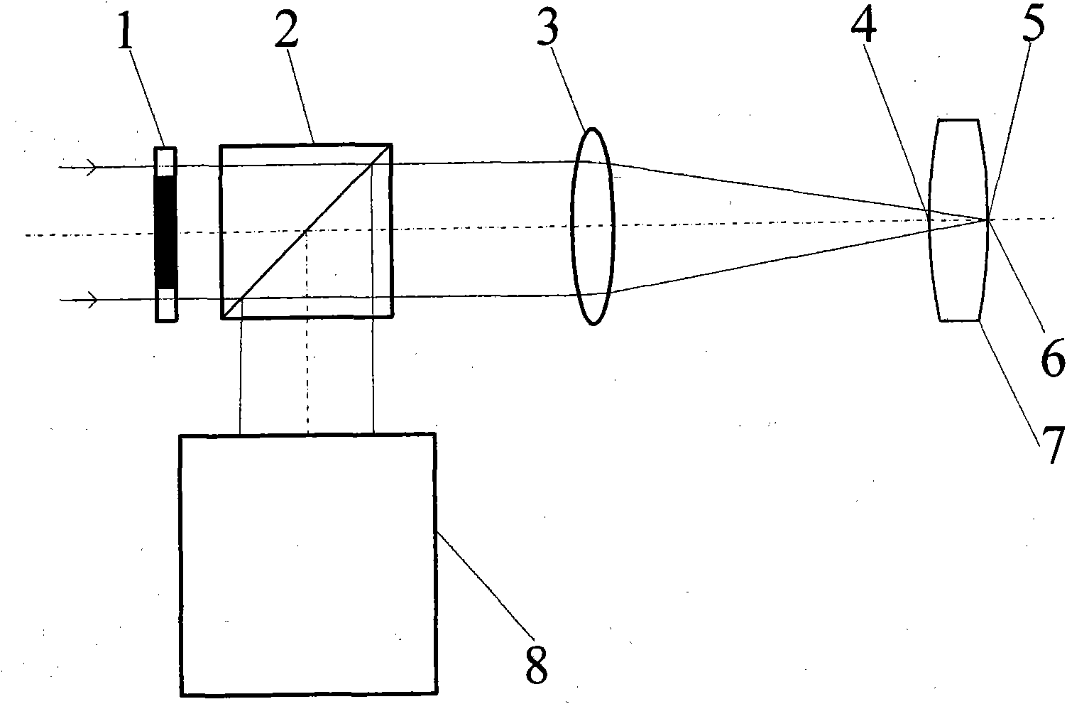
[0050] Such as figure 2 , Figure 5 with Figure 7 As shown, the measurement method of the center thickness of the differential confocal lens, the measurement steps are:

[0051] At first, start the measurement software in the main control computer 35, input relevant parameter, it mainly comprises the radius of curvature r of the front surface of the measured lens 7 1 =90.7908mm, air refractive index n 0 =1 and the refractive index of the measured lens 7 is n=1.5143.

[0052] Then, the collimated light source 28 is turned on, and the parallel light emitted by it passes through the annular pupil 1 with a light transmission diameter of 6.8mm-9.6mm, passes through the beam splitting system 2, and converges at the focal point through the 35mm objective lens 3 with a top focal length, forming a hollow The light cone, after the light is reflected by the surface of the measured lens 7, is reflected by the objective lens 3 and the beam splitting system 2 again and enters the beam...

Embodiment 2

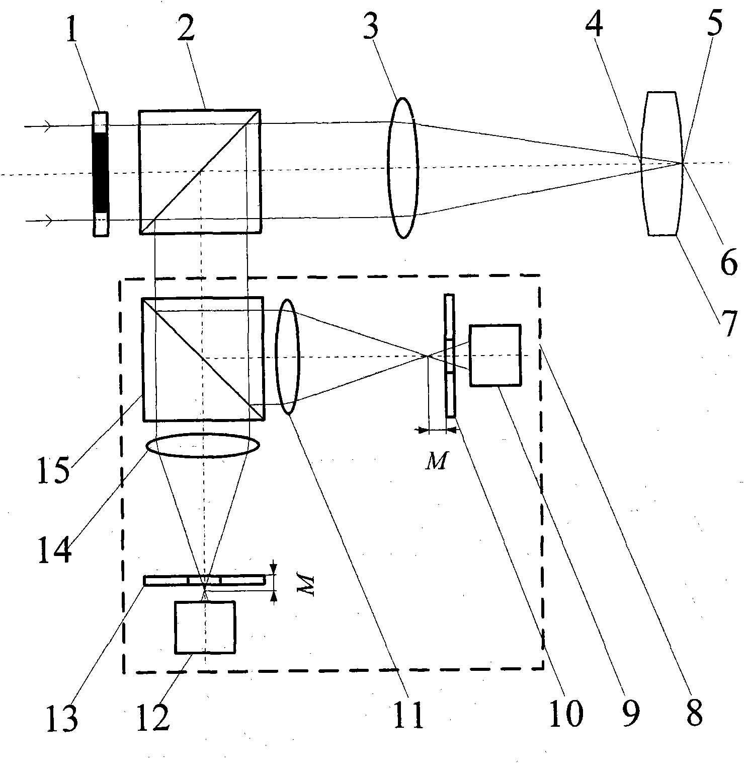
[0062] Such as image 3 , Figure 5 with Figure 7 As shown, the embodiment one figure 2 The differential confocal system in is replaced by image 3 The differential confocal system in the above can constitute the second embodiment. The difference from Embodiment 1 is that after the light enters the differential confocal system 8, the beam splitter 20 divides the light into two paths, the transmitted light illuminates the pre-focus CCD detector 18 after passing through the first lens 19, and the reflected light passes through the second lens 17 Back-illumination CCD detector 16 after focus. The remaining measurement methods and devices are the same as those in Example 1.

Embodiment 3

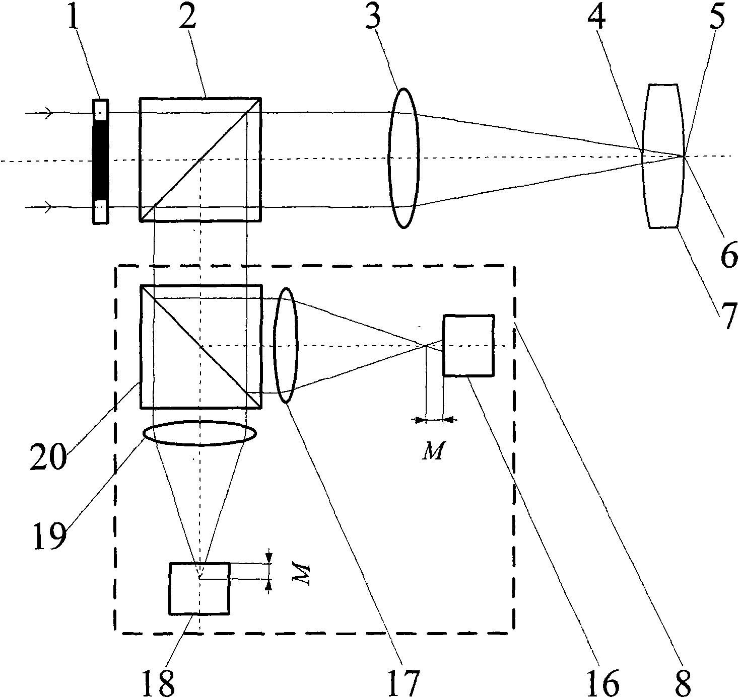
[0064] Such as Figure 4 , Figure 5 with Figure 7 As shown, the embodiment one figure 2 The differential confocal system in is replaced by Figure 4 The differential confocal system in the above can constitute the second embodiment. The difference from Embodiment 1 is that after the light enters the differential confocal system 8, the beam splitter 27 divides the light into two paths, and the transmitted light passes through the first lens 26 and the pre-focus microscopic objective lens 25 and passes through the first CCD detector 24. The surface is imaged, and the reflected light is imaged on the surface of the second CCD detector 21 after passing through the second lens 23 and the after-focus microscopic objective lens 22 . The remaining measurement methods and devices are the same as those in Example 1.

[0065] This embodiment realizes the non-contact high-precision measurement of the lens center thickness through a series of measures, realizes the method and devic...


PUM


Abstract

The invention belongs to the technical field of optical precision measurement, relating to a method and a device for measuring the central thickness of a differential confocal lens. The method comprises the steps of: firstly, respectively determining the positions of a vertex at the front surface and a vertex at the rear surface of a lens to be measured through a differential confocal and fixed-focal principle and obtaining position coordinates positioned two times by a differential confocal measuring head; and then calculating the central thickness of the lens by utilizing a ray tracing formula. Meanwhile, an annular pupil is introduced into a measuring optical path to shade a paraxial ray and form a hollow measuring light cone, which lightens the influence of aberration on a measuring result. The device comprises a beam splitting system, an objective lens, a differential confocal system, a length measuring system and a mobile guide rail; wherein the beam splitting system, the objective lens and the lens to be measured are sequentially placed in an emergent ray direction of a collimation light source and the differential confocal system is placed in the reflecting direction of the beam splitting system. By utilizing the differential confocal light cone to accurately position the surface of the lens, the invention realizes the non-contact high precision measurement of the central thickness of the lens.

Description

technical field [0001] The invention belongs to the technical field of optical precision measurement and can be used for non-contact high-precision measurement of lens center thickness. technical background [0002] In the field of optics, the measurement of lens center thickness is of great significance. Lens center thickness is an important parameter in the optical system, and its processing quality will have a great impact on the imaging quality of the optical system. Especially for lenses in high-performance optical systems such as lithography objective lenses and aerospace cameras, it is necessary to precisely adjust the axial gap, radial offset and optical axis deflection angle of the lens according to the curvature radius, refractive index and central thickness of the lens in the lens. adjustment. Taking the objective lens of lithography machine as an example, the deviation of the center thickness of each single lens will cause the aberration of the lithography obje...

Claims


Application Information

Patent Timeline
Patent Type & Authority Applications(China)
IPC IPC(8): G01B11/06G02B5/00
Inventor 赵维谦史立波孙若端邱丽荣刘大礼沙定国
Owner BEIJING INSTITUTE OF TECHNOLOGYGY
Why Eureka
Try Eureka