Automatic-control fuel feeding device of internal combustion engine and installation method thereof

A supply device and internal combustion engine technology, applied in the field of mechanical power, can solve problems such as unreasonable structure and component wear, and achieve the effects of simple structure, enhanced air stamping effect, and reduced working deviation

Inactive Publication Date: 2010-08-11
张普华
View PDF5 Cites 3 Cited by
  • Summary
  • Abstract
  • Description
  • Claims
  • Application Information

AI Technical Summary

Problems solved by technology

[0005] In order to solve the problems of unreasonable structure and component wear of the fuel mixing device of the internal combustion engine in the prior art, the present invention provides a simple structure, which can be installed on the carburetor and can automatically eliminate the negative pressure resistance when the internal combustion engine is working, and at the same time automatically and reasonably provide A device and a manufacturing method thereof for the intake of fresh air required for full combustion of the engine during operation, increasing power, reducing exhaust emission pollution, automatically and rationally adjusting the oxygen content required for the operation of the internal combustion engine, and fully mixing and atomizing the air and gasoline

Method used


Image

  • Automatic-control fuel feeding device of internal combustion engine and installation method thereof
  • Automatic-control fuel feeding device of internal combustion engine and installation method thereof
  • Automatic-control fuel feeding device of internal combustion engine and installation method thereof

Examples


Embodiment Construction

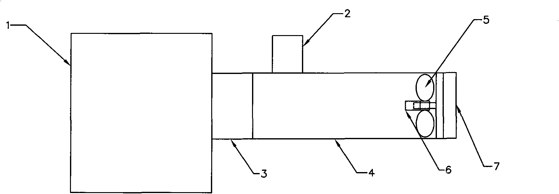
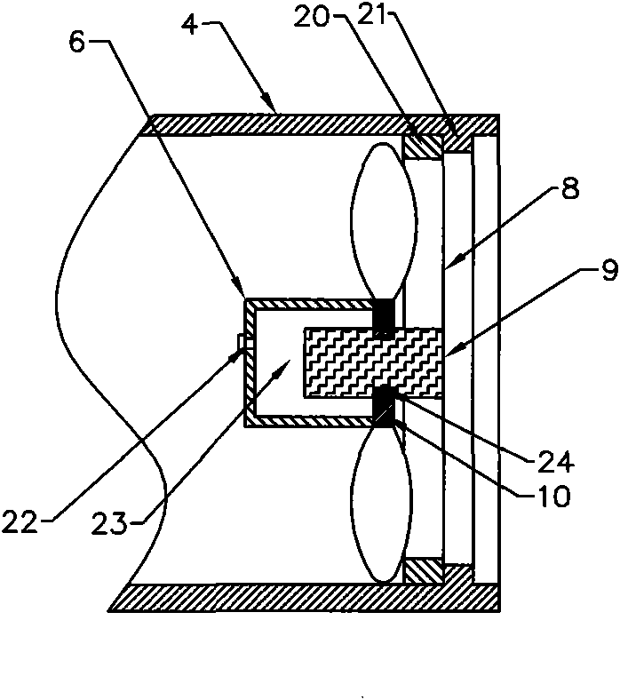
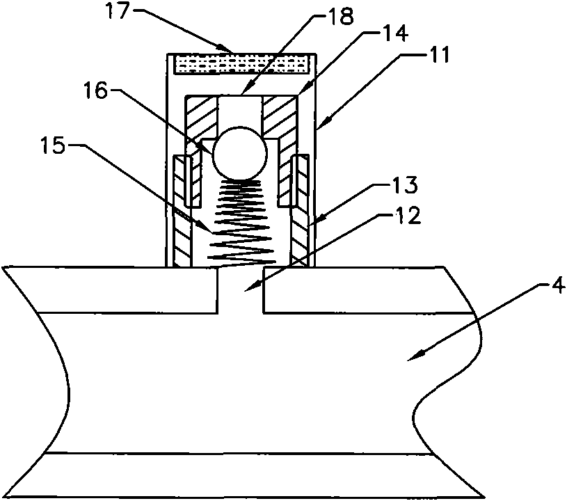
[0028] like figure 1 As shown, the internal combustion engine fuel atomization regulator of this program includes at least one automatic valve 2 and atomization fan, the automatic valve 2 is installed on the oil outlet pipe 4 at the oil outlet 3 of the carburetor 1, and the general through hole 12 is located at a distance from the outlet. At the 2 / 3 of the end of the oil pipe, more than two through holes need to be positioned symmetrically. When installing multiple fans and automatic valves, the distance between each automatic valve and the atomizing fan should not be less than the diameter of the through hole. The atomizing fan is installed in the outlet end 7 of the oil outlet pipe of the carburetor. The oil outlet pipe of the carburetor can be the body of the carburetor 1, or can be fixedly installed on the outlet of the carburetor 1 by means of welding, bolts or threads. Oil port 3, the equipment of this scheme can be flexibly installed depending on the size of the equipme...


PUM


Abstract

The invention relates to an automatic-control fuel feeding device of an internal combustion engine and an installation method thereof, in particular to a fuel mixing and optimizing device of an internal combustion engine and a manufacturing method thereof. The device of the invention comprises an automatic valve and an atomizing fan, wherein the automatic valve is installed on the wall of the oil outlet pipe of a carburetor, and the atomizing fan is installed in the oil outlet end of the oil outlet pipe. In the technical scheme of the invention, the device can adopt different automatic control valves according to actual requirements, automatically adjusts the air inflow according to the pressure change every time, reduces the error of the fuel mixture ratio, utilizes a sealing cavity installed on the atomizing fan to contain lubrication oil, keeps automatic lubrication when the atomizing fan works, reduces the working deviation caused by abrasion, automatically reduces the acceleration consumption under the normal conditions, automatically improves the efficiency, prolongs the service life of an engine, reduces the fuel consumption and automatically and simultaneously reduces the emission of harmful gases such as carbon monoxide, carbon dioxide, hydroxides, hydrocarbons and the like, thereby achieving the purpose of clean combustion.

Description

Technical field: [0001] The invention relates to the field of mechanical power, in particular to an internal combustion engine fuel mixing optimization device and a manufacturing method thereof. Background technique: [0002] The current gasoline internal combustion engine works by burning gasoline and air mixture. When a working stroke is over, the gasoline internal combustion engine is directly supplied with oil through the carburetor and high-pressure oil pipe, and the gasoline internal combustion engine will inhale gasoline-mixed fuel, and discharge the exhaust gas after combustion. However, when the internal combustion engine is working, the existing oil supply system makes the mixture of gasoline and air insufficient, and at the same time, negative pressure is generated in the cylinder, that is, the degree of vacuum, so that the proper mixed fuel cannot enter the cylinder. The resistance accelerates the wear of the transmission mechanism and the running mechanism. Whe...

Claims


Application Information

Patent Timeline
Patent Type & Authority Applications(China)
IPC IPC(8): F02M7/12F02M29/06
Inventor 张普华
Owner 张普华
Why Eureka
Try Eureka