
Method for producing PVD coatings

A coating and oxide technology, applied in the field of high-power pulse magnetron sputtering, can solve the problems of porous microstructure and unsuitable coating application

Inactive Publication Date: 2010-08-11
SANDVIK INTELLECTUAL PROPERTY AB
View PDF1 Cites 20 Cited by
  • Summary
  • Abstract
  • Description
  • Claims
  • Application Information

AI Technical Summary

Problems solved by technology

Although the layer contains nano-sized gamma alumina particles, the microstructure is porous making the deposited layer less suitable for many coating applications

Method used


Image

  • Method for producing PVD coatings
  • Method for producing PVD coatings
  • Method for producing PVD coatings

Examples


Embodiment 1

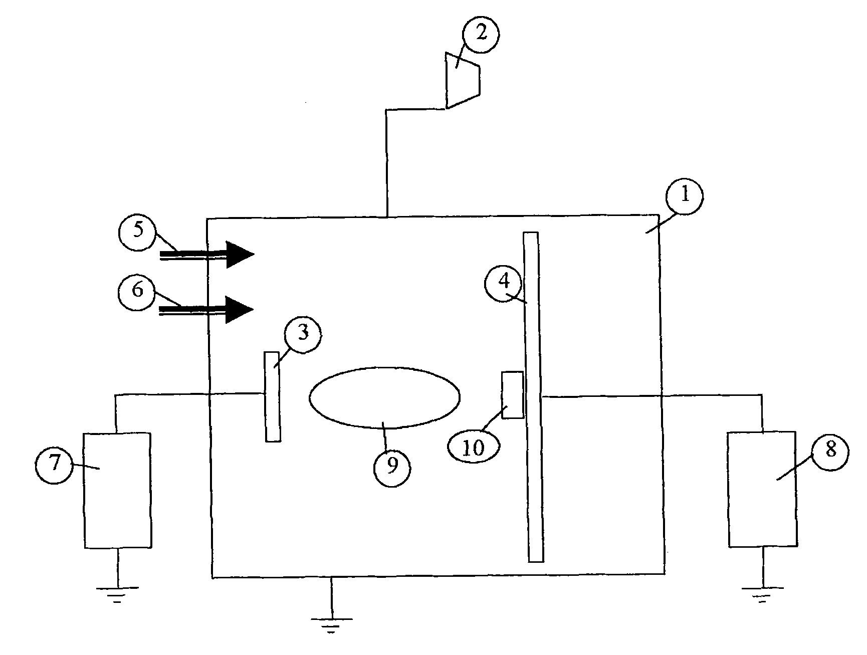
[0035] see figure 1 , cutting tool inserts of commercial grade H10F of composition WC10% Co and insert type SNUN1204 (dimensions 12x12x4 mm) were coated in an ultrahigh vacuum deposition system according to the following. Clean the blade (10) using standard procedures and place it on the base (4) operable to rotate during deposition with a 200cm 2 The area is at the position of about 10 cm above the magnetron sputtering target (3). The base (4) is electrically floating. The target (3) is an Al disk with a diameter of 50 mm and a thickness of 3 mm. Deposition was carried out in a vacuum chamber (1) which was first evacuated to 5×10 -7Torr. The blade (10) is heated to a surface temperature of approximately 600°C before deposition begins. Argon was used as sputtering gas, which was introduced into the chamber (1 ) via a first mass flow controller (5). A constant flow of 100 seem argon was used, which resulted in a total pressure of 6 mTorr in chamber (1).

[0036] Depositi...


PUM

PropertyMeasurementUnit
diameteraaaaaaaaaa
thicknessaaaaaaaaaa

Abstract

The present invention relates to a method of producing coatings of metal oxide, nitride or carbide or mixtures thereof, whereby operating a High Power Impulse Magnetron Sputtering, HIPIMS, discharged on one or more target (s) (3), in an argon and reactive gas mixture (5, 6), at peak pulse power higher than 200 Wcm-2, in which the deposition rate is improved and in the need for partial reactive gas pressure feedback systems is eliminated.

Description

technical field [0001] The present invention relates to a high power pulsed magnetron sputtering (HIPIMS) method with high deposition rates. Background technique [0002] Hard PVD coatings are often used to protect the underlying material from oxidation and wear. Such a hard coating can be deposited by PVD methods such as reactive magnetron sputtering. The use of reactive sputtering gases creates problems because on the surface of the target the desired material forms a layer with different properties compared to the metal surface, for example an electrically insulating layer. In particular, when the sputtering yield or electron emission rate of the reactive target surface differs from that of the metal surface, hysteresis effects occur which render the method unstable. [0003] In order to avoid the formation of thick reactive layers on the target, established PVD techniques teach how to reactively deposit hard coatings by means of double magnetrons, double magnetron sput...

Claims


Application Information

Patent Timeline
Patent Type & Authority Applications(China)
IPC IPC(8): C23C14/08
CPCC23C14/081H01J37/3467C23C14/35C23C14/0641C23C14/0635C23C30/005
Inventor 埃里克·沃林乌尔夫·赫尔默松
Owner SANDVIK INTELLECTUAL PROPERTY AB
Learn More