Rotating armature controller

A technology for rotating electrical machines and control devices, applied in control devices, motor generator control, AC motor control, etc., can solve the problems of increased electromagnetic noise, stronger electric field noise, and large energization current, and achieves noise reduction and conversion. The effect of reduced frequency and reduced likelihood

Active Publication Date: 2010-08-11
AISIN AW CO LTD
View PDF2 Cites 12 Cited by
  • Summary
  • Abstract
  • Description
  • Claims
  • Application Information

AI Technical Summary

Problems solved by technology

In the case of wheel drive motors, since the energizing current is large, the switching noise is strong, and there is a high possibility that the rotation detection signal of the resolver will be disturbed.
[0011] Assuming that if the waveform of the rotation detection signal (sine wave or cosine wave) of the resolver is deformed due to the action of noise, the rotation angle detection value θ of the motor will be wrong, and the motor cannot be controlled correctly by vector control.
In particular, in the three-phase modulation mode, since the switching times of the inverter are many, if it becomes a high torque (high current) output, the electromagnetic noise will increase due to the increase of the high-order harmonic component of the current. Larger, the possibility of disturbance of the rotation detection signal of the resolver becomes higher
In addition, in the three-phase modulation mode, if the number of revolutions increases, the secondary side voltage (output voltage) of the converter (booster circuit) increases, so the inverter voltage is increased, and the switching of the inverter is changed. The generated electric field noise becomes stronger, and the possibility of disturbance of the rotation detection signal of the resolver becomes higher.

Method used


Image

  • Rotating armature controller
  • Rotating armature controller
  • Rotating armature controller

Examples


no. 1 Embodiment

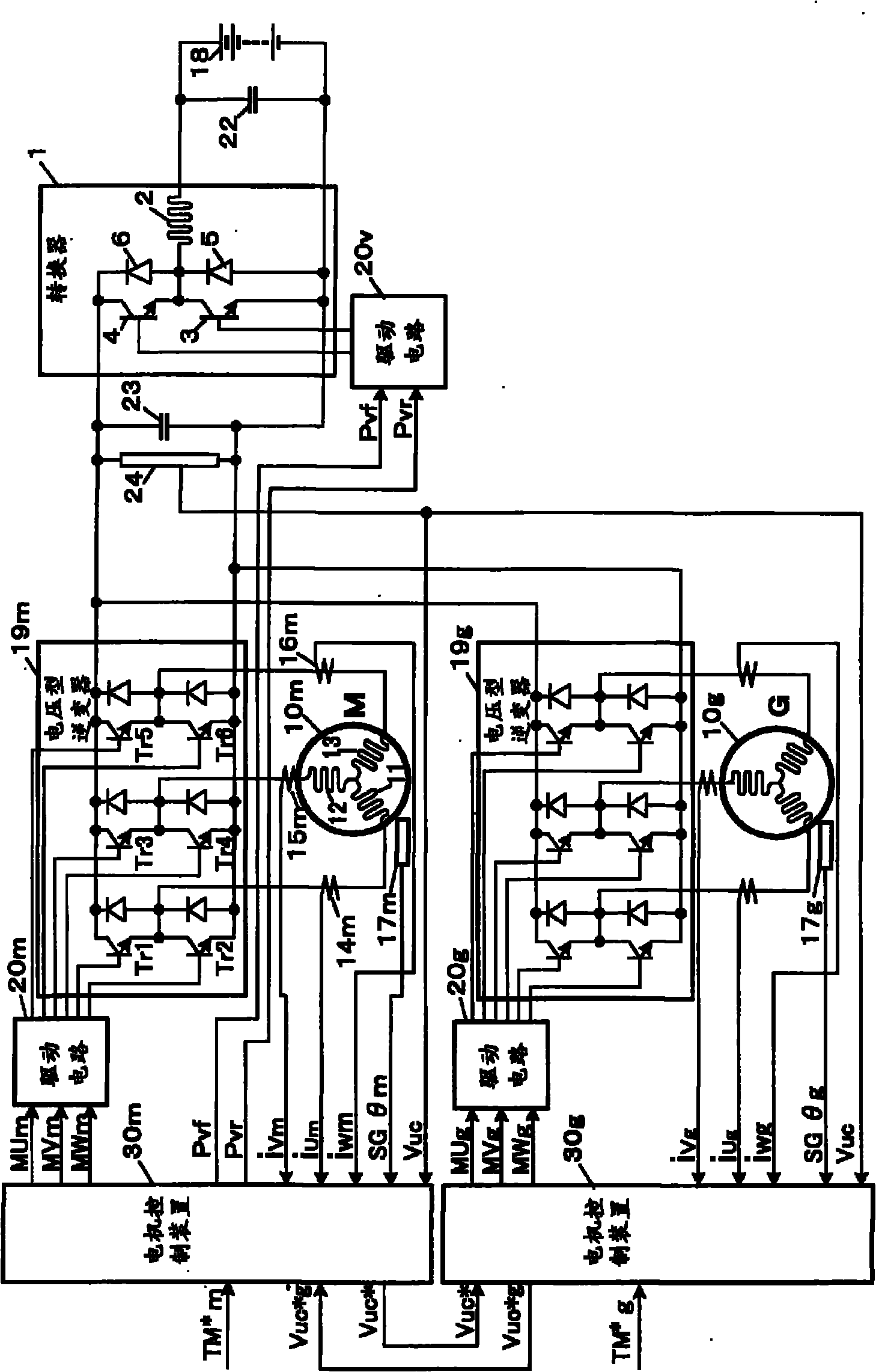
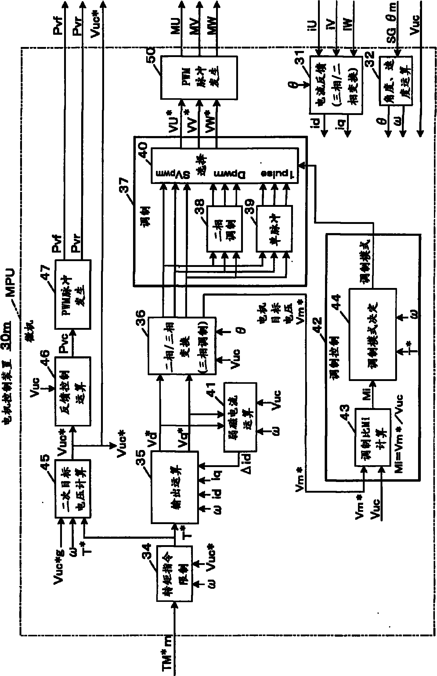
[0075] figure 1 The outline of the first embodiment of the present invention is shown. The motor (electric motor) 10m, which is the first rotating electrical machine to be controlled, is a permanent magnet type synchronous motor mounted on a vehicle for rotationally driving wheels in this embodiment. A permanent magnet is built into the rotor and a stator has a Three-phase coils 11 to 13 of U-phase, V-phase, and W-phase. The voltage source inverter 19m as the first inverter supplies electric power of the battery 18 on the vehicle to the motor 10m. A rotor of a first resolver 17m for detecting the rotor magnetic pole position is connected to the rotor of the motor 10m. The resolver 17m generates an analog voltage (rotation angle signal) SGθm representing its rotor rotation angle, and supplies it to the motor control device 30m.

[0076] The primary side capacitor 22 is connected to the battery 18 which is a storage battery on the vehicle when the electric device on the vehi...

no. 2 Embodiment

[0129] Figure 5 The outline of the second embodiment of the present invention is shown in . The rotating electric machine (motor) 10m that is the control object is a permanent magnet synchronous motor mounted on a vehicle for rotationally driving the wheels in this embodiment. A permanent magnet is built into the rotor, and a U phase, V phase, and V phase are provided on the stator. Phase and W-phase three-phase coils 11 to 13 . The voltage source inverter 19m as the first inverter supplies electric power of the battery 18 on the vehicle to the motor 10m. The rotor of the first resolver 17m for detecting the rotor magnetic pole position is connected to the rotor of the motor 10m. The resolver 17m generates an analog voltage (rotation angle signal) SGθm representing its rotor rotation angle, and supplies it to the motor control device 30m.

[0130] In the second embodiment, since the battery voltage Vdc is applied to the inverter instead of the converter for boosting and ou...


PUM


Abstract

A motor driving error is prevented. In concrete, disturbance in a rotation detection signal of a resolver due to motor noise is reduced. An inverter is controlled to set output torque of a rotating armature at target torque using the target torque, rotation speed and a rotation angle of the rotating armature. Three-phase/two-phase modulation takes place, wherein control of the inverter is changedfrom three-phase modulation to two-phase modulation when a modulation ratio expressed as a ratio of voltage applied to the rotating armature for voltage input to the inverter is larger than three-phase/two-phase modulation changeover boundary. Even in a three-phase modulation region where the modulation ratio is smaller than the three-phase/two-phase modulation changeover boundary, the modulationis changed over to the two-phase modulation in a specific region where torque of the rotating armature corresponding to the mentioned boundary, a torque threshold lower than the rotation speed and electric noise applied by the rotating armature exceeding the rotation speed threshold to the resolver are large. In an embodiment using step-up voltage (Vuc), the torque threshold is made to be the lower the higher the step-up voltage, to enlarge the specific region.

Description

technical field [0001] The present invention relates to a rotating electrical machine control device that controls electric power supplied from an inverter to a motor and generated power in the opposite direction, and in particular, relates to control of an inverter control mode, that is, a modulation mode, in a rotating electrical machine control device including a resolver. The rotating electrical machine control device of the present invention can be used, for example, in an electric vehicle (EV) that drives wheels by an electric motor, and in addition to the electric motor, also includes a fuel engine and a generator that is rotationally driven by the engine (sometimes referred to as an electric motor or electric generator). motor generator) for hybrid electric vehicles (HEV). Background technique [0002] The three-phase modulation mode of the three-phase inverter generates three-phase alternating current by means of three-phase PWM switching conversion and applies it t...

Claims


Application Information

Patent Timeline
Patent Type & Authority Applications(China)
IPC IPC(8): H02P6/08H02P21/00H02P27/04H02P6/06H02P6/15H02P6/17H02P6/28H02P21/05H02P21/13H02P21/22H02P23/04H02P27/08
CPCB60L2240/423B60L11/1803H02P21/0089Y02T10/7005H02P21/06Y02T10/70B60L11/18B60L2240/421B60L15/007Y02T10/643B60L15/025B60L11/14B60L11/123Y02T10/642B60L2270/142B60L50/61B60L50/16B60L50/51Y02T10/64Y02T10/62Y02T10/7072
Inventor 西村圭亮榊原益穗中川善也大野佳纪
Owner AISIN AW CO LTD
Why Eureka
Try Eureka