Hydraulic device for spindle brake of wind generating set
A technology of wind turbines and hydraulic devices, applied in the field of hydraulic devices, can solve problems such as small braking torque and complex system structure, and achieve the effects of low working oil pressure, small volume and large braking torque
- Summary
- Abstract
- Description
- Claims
- Application Information
AI Technical Summary
Problems solved by technology
Method used
Image
Examples
specific Embodiment approach 1
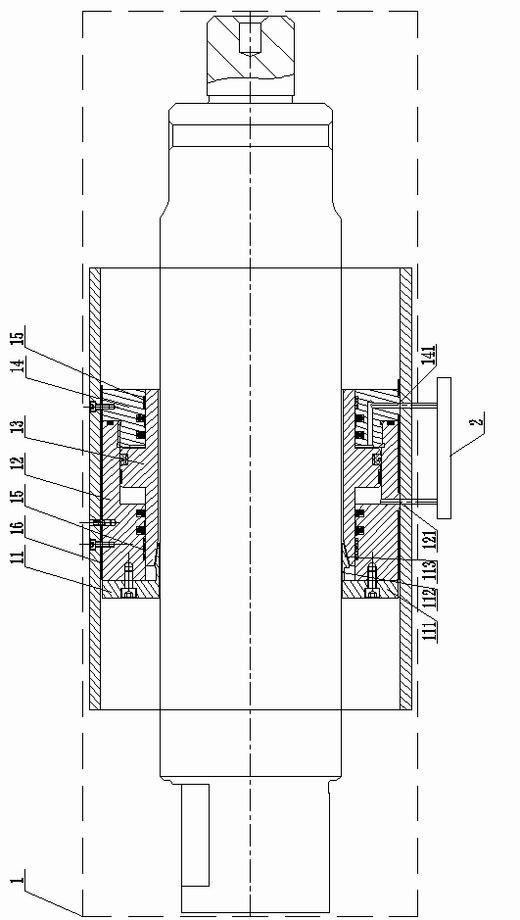
[0014] Specific implementation mode one: the following combination figure 1 and figure 2 Describe this embodiment, the hydraulic device described in this embodiment is a set, the hydraulic device is composed of a mechanical structure 1 and a hydraulic control system 2, the mechanical structure 1 is a hollow hydraulic cylinder, it consists of a brake block 11, a hollow oil cylinder 12. Composed of piston rod 13, hydraulic cylinder head 14, multiple guide sleeves 15 and bushing 16,
[0015] The brake block 11 is composed of an end ring segment 111, a middle ring segment 112 and a wedge-shaped ring segment 113 with equal inner diameters, and the end ring segment 111, the middle ring segment 112 and the wedge-shaped ring segment 113 are fixed in sequence from one side as a whole The large-diameter end face of the wedge-shaped ring segment 113 is connected to one side end face of the intermediate ring segment 112, and the outer surface of the intermediate ring segment 112 forms ...
specific Embodiment approach 2
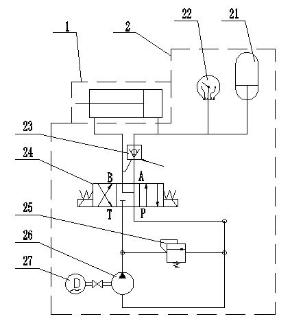
[0022] Specific implementation mode two: the following combination figure 2 Describe this embodiment, the difference between this embodiment and Embodiment 1 is that the hydraulic control system 2 is composed of an accumulator 21, an electric contact pressure gauge 22, a one-way valve 23, an electromagnetic reversing valve 24, and a relief valve 25. , quantitative pump 26 and motor 27,
[0023] The output shaft of the motor 27 is connected to the input shaft of the quantitative pump 26, the T port of the electromagnetic reversing valve 24 is connected to the inlet of the quantitative pump 26 through the pipeline, and the P port of the electromagnetic reversing valve 24 is connected to the outlet of the quantitative pump 26 through the pipeline. The B port of the reversing valve 24 is connected to the oil return port 121 on the hollow oil cylinder 12 in the mechanical structure 1 through the oil return pipeline, and the A port of the electromagnetic reversing valve 24 is conne...
specific Embodiment approach 3
[0026] Embodiment 3: The difference between this embodiment and Embodiment 1 is that the brake block 11 is composed of two or more arc segments segmented along the radial direction of the axis.
[0027] If the brake block 11 is to form radial deformation, it must be formed by combining more than two arc segments. If it is an annular integral brake block 11, it cannot complete the clamping effect on the brake shaft.
PUM
 Abstract
Description
Claims
Application Information
 - R&D
- Intellectual Property
- Life Sciences
- Materials
- Tech Scout
- Unparalleled Data Quality
- Higher Quality Content
- 60% Fewer Hallucinations
Browse by: Latest US Patents, China's latest patents, Technical Efficacy Thesaurus, Application Domain, Technology Topic, Popular Technical Reports.
© 2025 PatSnap. All rights reserved.Legal|Privacy policy|Modern Slavery Act Transparency Statement|Sitemap|About US| Contact US: help@patsnap.com


