
Hydraulic device for spindle brake of wind generating set

A technology for wind turbines and hydraulic devices, which is applied in the field of hydraulic devices, can solve the problems of complex system structure and small braking torque, and achieve the effects of small volume, low working oil pressure and large braking torque

Inactive Publication Date: 2011-11-02
HARBIN INST OF TECH
View PDF0 Cites 0 Cited by
  • Summary
  • Abstract
  • Description
  • Claims
  • Application Information

AI Technical Summary

Problems solved by technology

[0005] The purpose of the present invention is to provide a hydraulic device for braking the main shaft of a wind power generating set in order to solve the problem that the existing wind power generating set main shaft brake system adopts disc brakes, its braking torque is small, and the system structure is complicated.

Method used


Image

  • Hydraulic device for spindle brake of wind generating set
  • Hydraulic device for spindle brake of wind generating set
  • Hydraulic device for spindle brake of wind generating set

Examples


specific Embodiment approach 1

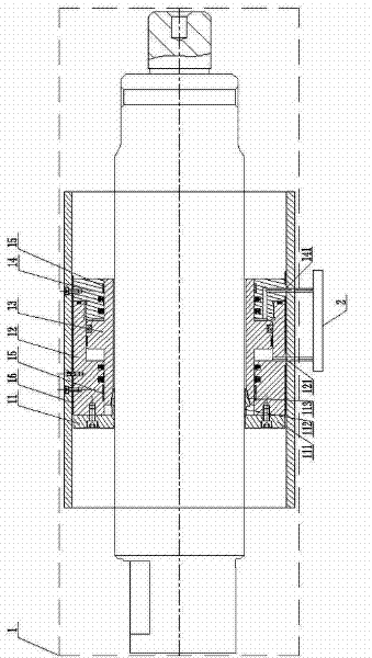
[0014] Specific implementation mode one: the following combination figure 1 and figure 2 Describe this embodiment, the hydraulic device described in this embodiment is a set, the hydraulic device is composed of a mechanical structure 1 and a hydraulic control system 2, the mechanical structure 1 is a hollow hydraulic cylinder, it consists of a brake block 11, a hollow oil cylinder 12. Composed of piston rod 13, hydraulic cylinder head 14, multiple guide sleeves 15 and bushing 16,

[0015] The brake block 11 is composed of an end ring segment 111, a middle ring segment 112 and a wedge-shaped ring segment 113 with equal inner diameters, and the end ring segment 111, the middle ring segment 112 and the wedge-shaped ring segment 113 are fixed in sequence from one side as a whole The large-diameter end face of the wedge-shaped ring segment 113 is connected to one side end face of the intermediate ring segment 112, and the outer surface of the intermediate ring segment 112 forms ...

specific Embodiment approach 2

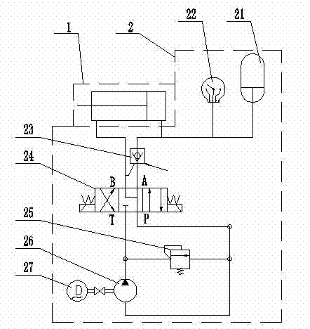
[0022] Specific implementation mode two: the following combination figure 2 Describe this embodiment, the difference between this embodiment and Embodiment 1 is that the hydraulic control system 2 is composed of an accumulator 21, an electric contact pressure gauge 22, a one-way valve 23, an electromagnetic reversing valve 24, and a relief valve 25. , quantitative pump 26 and motor 27,

[0023] The output shaft of the motor 27 is connected to the input shaft of the quantitative pump 26, the T port of the electromagnetic reversing valve 24 is connected to the inlet of the quantitative pump 26 through the pipeline, and the P port of the electromagnetic reversing valve 24 is connected to the outlet of the quantitative pump 26 through the pipeline. The B port of the reversing valve 24 is connected to the oil return port 121 on the hollow oil cylinder 12 in the mechanical structure 1 through the oil return pipeline, and the A port of the electromagnetic reversing valve 24 is conne...

specific Embodiment approach 3

[0026] Embodiment 3: The difference between this embodiment and Embodiment 1 is that the brake block 11 is composed of two or more arc segments segmented along the radial direction of the axis.

[0027] If the brake block 11 is to form radial deformation, it must be formed by combining more than two arc segments. If it is an annular integral brake block 11, it cannot complete the clamping effect on the brake shaft.


PUM


Abstract

A hydraulic device for a spindle brake of a wind generating set belongs to the field of wind power equipment braking and solves the problems that because spindle brake of the existing wind generating set adopts disc brake, the brake torque is little, and the system structure is complex. In the invention, an intermediate ring section of a braking block forms a ring groove between an end ring section and a wedge surface ring section, the end ring section is connected with a large end surface of a hollow cylinder, a piston rod is arranged in the interior of the hollow cylinder, the ring bulge ofthe piston rod is matched with the inner ring surface of a shoulder structure of the hollow cylinder, the inner ring surface of the bottom end of the piston rod is in clearance fit with the external surface of the wedge surface ring section, a hydraulic cylinder cover is sealed and matched with the hollow cylinder and the piston rod, a bush is arranged on the hydraulic cylinder cover and the external ring surface of the hollow cylinder, a guide sleeve is arranged between the piston rod and the hydraulic cylinder cover and between the piston rod and the hollow cylinder, an oil pipeline of a hydraulic control system is connected on an oil inlet of the hydraulic cylinder cover, and an oil return pipeline is connected with an oil return port on the hollow cylinder. The invention is used for braking of the spindle of the wind generating set.

Description

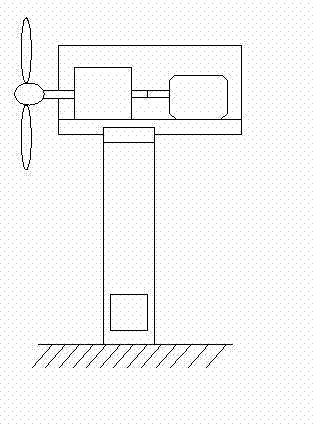
technical field [0001] The invention relates to a hydraulic device for braking the main shaft of a wind power generating set, which belongs to the field of braking of wind power generating equipment. Background technique [0002] Wind energy is the conversion form of solar energy, and it is a renewable natural energy source. It does not produce any pollution and is one of the main new power sources for the sustainable development of human society and economy. [0003] At present, commercial large-scale wind turbines generally use horizontal-axis wind turbines, which are composed of impellers, speed-increasing gearboxes, generators, yaw systems, control systems, towers and other components, such as image 3 As shown, the impeller is formed by the blades with excellent aerodynamic performance installed on the hub, which converts wind energy into mechanical energy, which is transmitted to the speed-up gearbox through the transmission system to increase the speed, and then transm...

Claims


Application Information

Patent Timeline
Patent Type & Authority Patents(China)
IPC IPC(8): F03D7/00F16D49/00F15B1/02F03D9/00F03D9/25
CPCY02E10/723Y02E10/72
Inventor 姜继海孙毅王克龙刘成强
Owner HARBIN INST OF TECH
Learn More