Dry distillation system for oil shales

A technology of oil shale and dry distillation, which is applied in special forms of dry distillation, direct heating dry distillation, petroleum industry, etc., can solve the problems of reducing the dust content of dry distillation gas, reducing operating costs, etc., and achieves low operating cost, improved utilization rate, and technical performance reliable effect

Inactive Publication Date: 2013-10-16
曹志德 +2
View PDF6 Cites 0 Cited by
  • Summary
  • Abstract
  • Description
  • Claims
  • Application Information

AI Technical Summary

Problems solved by technology

[0011] The purpose of the present invention is to overcome the above-mentioned deficiencies in the prior art and provide a method that can complete the crushing, screening, furnace loading, heating, collection of shale retort gas, cooling and collection of shale semi-coke to obtain more oil shale. The oil shale carbonization system with good technical performance solves the problem that many small-sized particles contained in the oil shale raw material are easy to leak from the grate and the semi-coke particles are easy to get stuck in the gap of the grate without falling off, further reducing the heat load When the gas passes through the oil shale material layer in the furnace, the amount of powder in the material layer is entrained to reduce the dust content of the retort gas and reduce operating costs

Method used


Image

  • Dry distillation system for oil shales
  • Dry distillation system for oil shales
  • Dry distillation system for oil shales

Examples


Embodiment 1

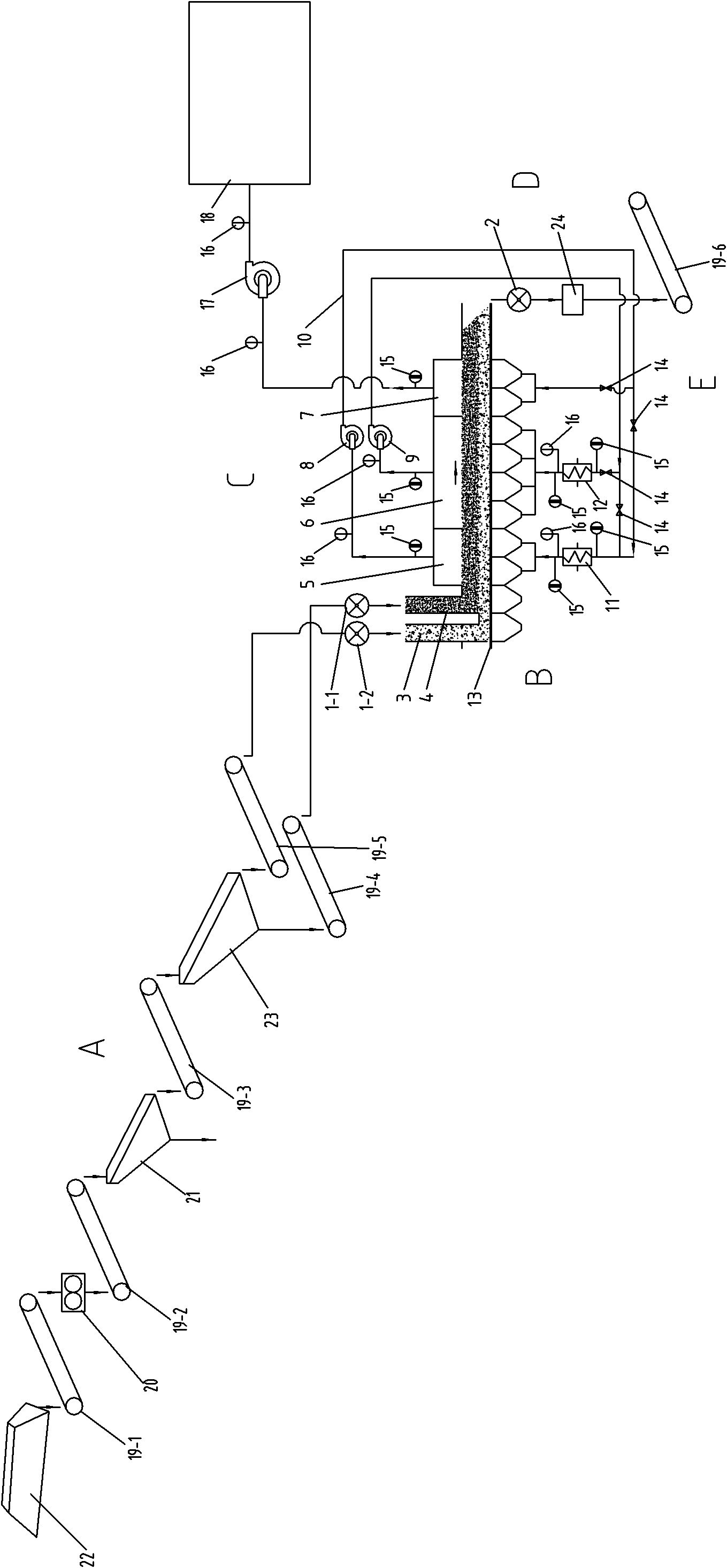
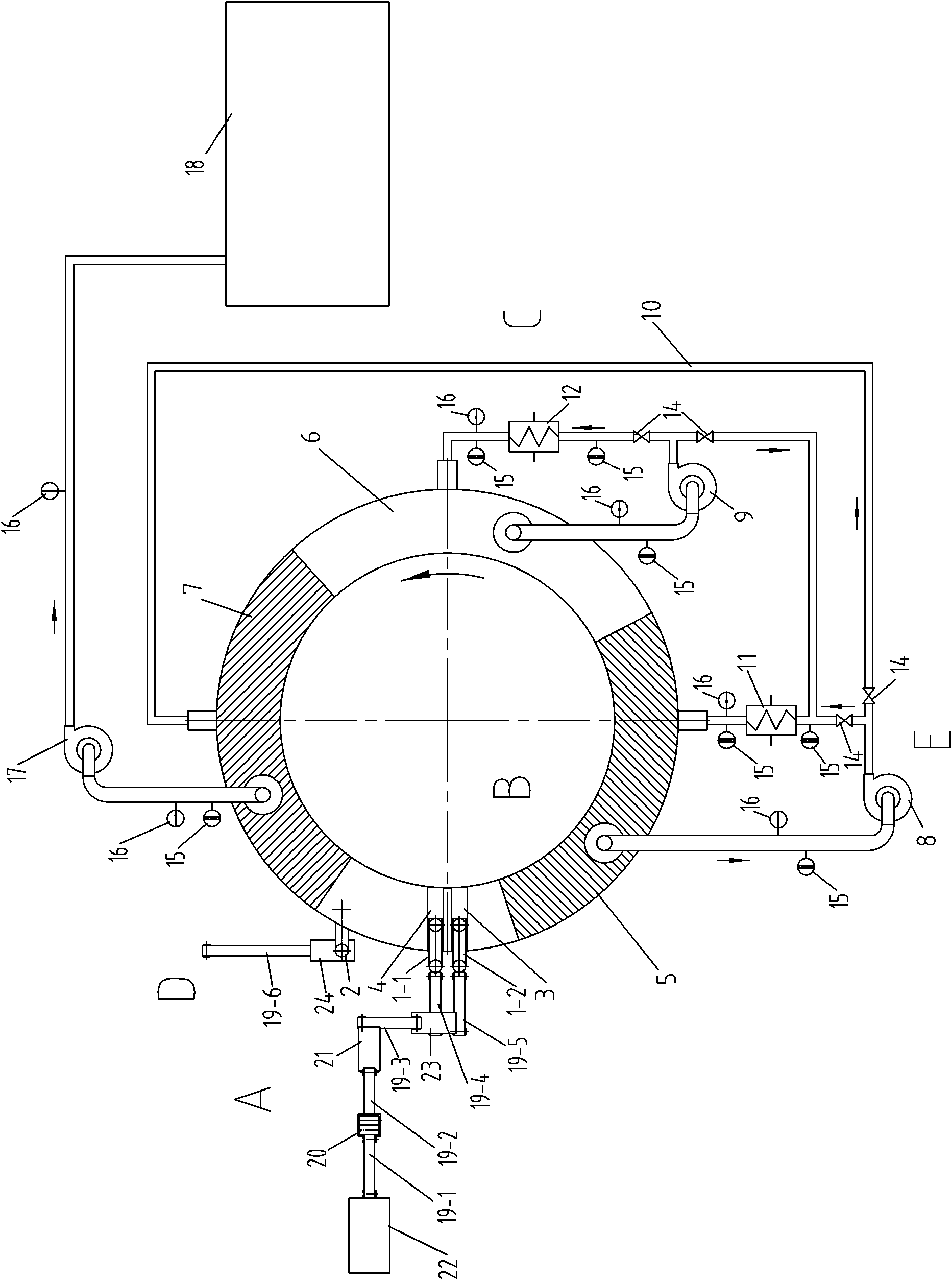
[0030] refer to figure 1 , figure 2 As shown, an oil shale retort system mainly includes a distributing system A, a reaction furnace B, a retort gas circulation system C, a cooling system D, a control system E and related conveying and output pipelines, related control circuits, etc.; its distributing system A The reaction furnace B is connected to the reaction furnace B through the relevant delivery and output pipelines, and the reaction furnace B is connected to the retort gas circulation system C through the control system E and the relevant delivery and output pipelines. Oil shale retort system for shale crushing, screening, furnace loading, heating, collection of shale retort gas, cooling and collection of shale semi-coke.

[0031] The material distribution system A mainly includes a sealed feeder 1, a large-size oil shale feed bin 3 for the reaction furnace, a small-size oil shale feed bin 4 for the reaction furnace, a conveyor belt conveyor 19, and a crusher 20 , vib...

Embodiment 2

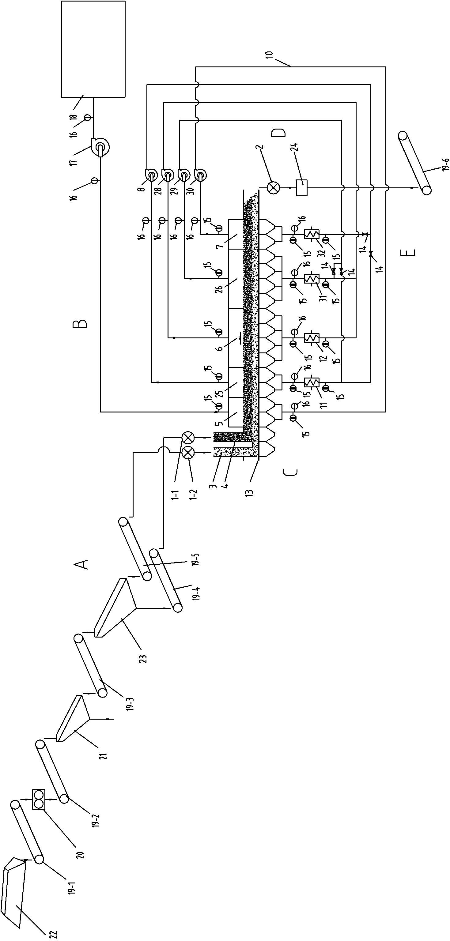
[0038] refer to image 3 , Figure 4 As shown, the reaction furnace B mainly includes a heating section 5, a heating section 25, a reaction section 6, a reaction section 26, and a cooling section 7. The retort gas circulation system C also includes a retort gas circulation fan 28 in the reaction section. , 29, and the retort gas circulation fan 30 in the cooling section, the retort gas heater 31 in the reaction section, the retort gas heater 32 in the cooling section, etc.; the retort gas circulation fan 8 in the heating section is connected to the retort gas heater in the heating section through the retort gas circulation pipeline 10 11. The second heating section 25 and the retort gas heater 32 and cooling section 7 in the cooling section; the retort gas circulation fan 28 in the reaction section is connected to the reaction section heater 12 and the reaction section 6 through the retort gas circulation pipeline 10, and is connected to the reaction section retort gas heating...

Embodiment 3

[0041] refer to Figure 5 , Figure 6 As shown, the reaction furnace B mainly includes a heating section 5, a heating section 25, a reaction section 6, a reaction section 26, a cooling section 7, and a cooling section 27. The retort gas circulation system C includes a heating section Retort gas circulation fan 8, retort gas circulation fan 28, 29 in the reaction section, retort gas circulation fan 30, fan 17 in the cooling section, retort gas heater 31 in the reaction section, retort gas heater 32 in the cooling section, condensate collection device 33, etc.; The retort gas circulation fan 8 in the heating section is connected to the heating section 5, the condensate collection device 33, and the second cooling section 27 through the retort gas circulation pipeline 10; The heater 11 and the second heating section 25 are connected to the retort gas heater 32 in the cooling section and the first cooling section 7; The retort gas heater 31 in the reaction section, the second re...


PUM

PropertyMeasurementUnit
particle diameteraaaaaaaaaa

Abstract

The invention relates to a dry distillation system for oil shales. In the dry distillation system, a material distributing system is communicated with a reaction furnace by related charging and discharging pipelines, the reaction furnace is communicated with a dry distillation gas circulation system by related charging and discharging pipelines, and the dry distillation gas circulation system is communicated with a cooling system by related charging and discharging pipelines; and a grading screen of the material distributing system is communicated with a belt conveyor and a sealing feeder to input the big-gain diameter oil shales to and spread the big-gain diameter oil shales on a fire grate of the reaction furnace and to input the small-gain diameter oil shales to and spread the small-gain diameter oil shales on the big-gain diameter oil shale layer. The dry distillation system has the advantages of realizing crushing, screening, furnace charging and heating of the oil shales, collection of the oil shale dry distillation gas, cooling and collection of shale semicoke and the like, solving the problem that the small-grain size grains are easily leaked out of the fire grate and the problem that the semicoke grains are easily clipped in the seams of the fire grate and do not fall off, improving the utilization ratio of the oil shales, reducing the resistance of the material layers, avoiding the loss of the powder in the material layers, effectively lowering the dust content, lowering the tapping temperature of the semicoke, improving the utilization efficiency of the heat energy, along with reliable performance, low-carbon environmental protection and easy industrialized extraction of the oil shales.

Description

technical field [0001] The invention belongs to the technical field of extracting shale oil from oil shale, and relates to an oil shale carbonization system. Background technique [0002] Oil shale is an important potential energy source with huge reserves. Among fossil fuels, its reserves are converted into calorific value and rank second only to coal. If it is converted into shale oil, the world's oil shale reserves are about 475 billion tons, equivalent to several times the proven recoverable reserves of natural crude oil in the world. The development and application of oil shale has a history of more than 200 years, and the development and utilization of oil shale energy mainly lies in the production of shale oil. [0003] During the Second World War, due to the sharp increase in oil demand and the sharp rise in oil prices, many countries experienced an upsurge in oil shale development. In peacetime after World War II, due to the discovery and massive development of ch...

Claims


Application Information

Patent Timeline
Patent Type & Authority Patents(China)
IPC IPC(8): C10B53/06C10B49/02C10B15/00
Inventor 曹志德杨东进米志刚
Owner 曹志德
Why Eureka
Try Eureka