Flow battery

A flow battery and liquid flow technology, applied in secondary batteries, regenerative fuel cells, circuits, etc., can solve the problems of difficult processing, low energy efficiency, low power density, etc., to improve power density and energy efficiency, and improve current. Efficiency and energy efficiency, effect of reducing self-discharge current

Inactive Publication Date: 2010-08-25
GOLDEN ENERGY FUEL CELL
View PDF0 Cites 44 Cited by
  • Summary
  • Abstract
  • Description
  • Claims
  • Application Information

AI Technical Summary

Problems solved by technology

[0003] Existing flow batteries are usually composed of ion exchange membranes, flow field plates, diversion nets, turbulence nets, electrodes, conductive plates, etc., which have many components, complex and uncompact structures, difficult processing, inconvenient assembly, large thicknes

Method used


Image

  • Flow battery
  • Flow battery
  • Flow battery

Examples


Embodiment Construction

[0041] Labels in the figure:

[0042] 1 Positive flow frame plate 2 Negative flow frame plate 3 Conductive plate

[0043] 4 positive electrode 5 ion exchange membrane 6 negative electrode

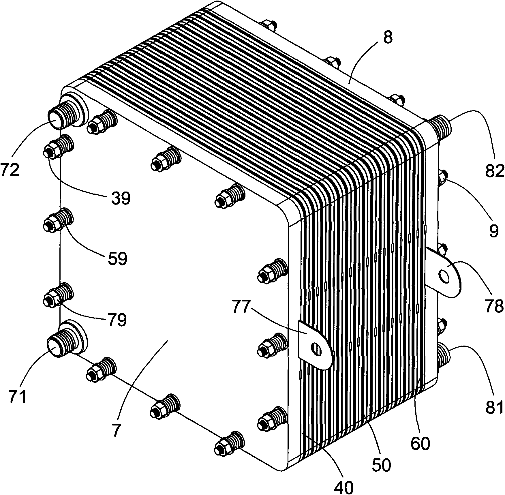
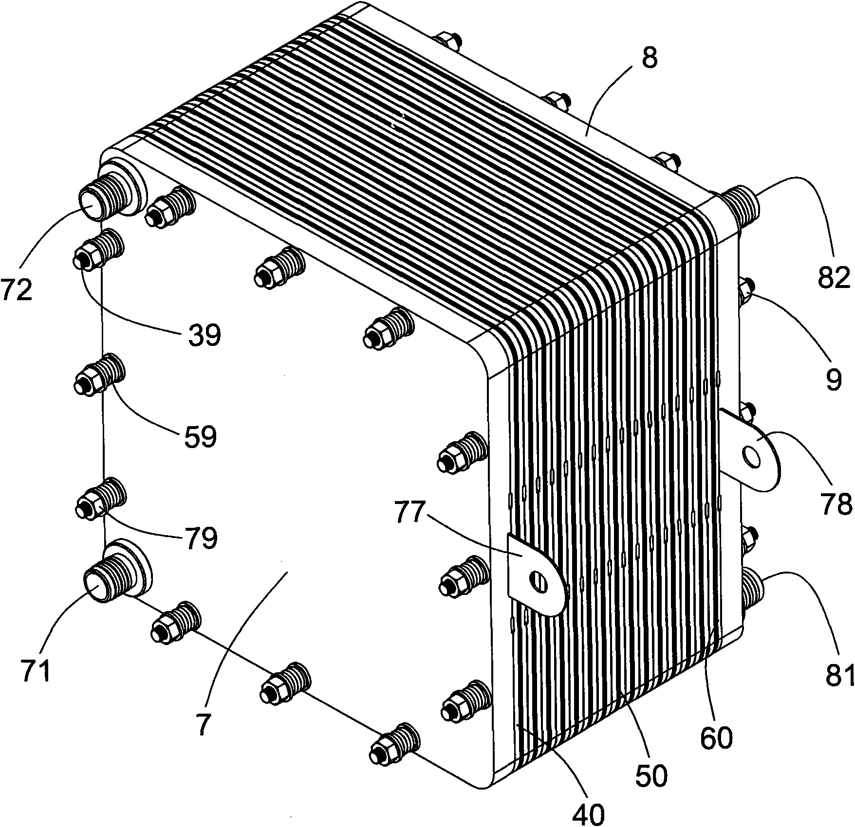
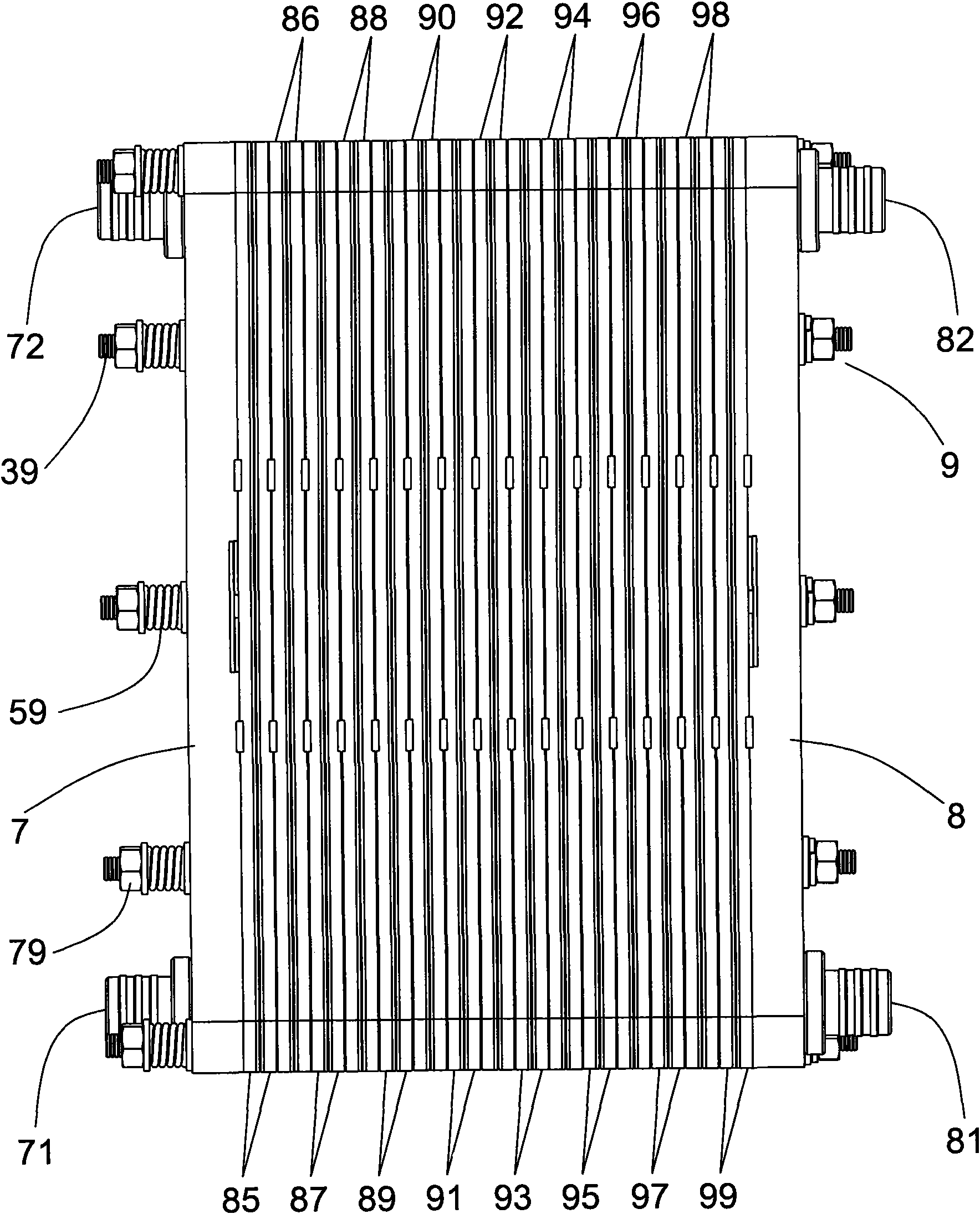
[0044] 7 Positive end pressure plate 8 Negative end pressure plate 9 Fasteners

[0045] 10 inner frame 11 liquid inlet hole 12 liquid outlet hole

[0046] 13 Liquid outlet hole 14 Liquid outlet hole 15 Locating pin

[0047] 16 Positioning hole 17 Cover plate 18 Cover plate

[0048] 19 Annular concave table 20 Inner frame 21 Liquid inlet hole

[0049] 22 Liquid hole 23 Liquid hole 24 Liquid outlet

[0050] 25 positioning pin 26 positioning hole 27 cover plate

[0051] 28 Cover plate 29 Annular concave platform 30 "O" type sealing ring

[0052] 31 branch flow channel 32 narrow comb groove 33 long straight groove

[0053] 34 narrow comb slot 35 long straight slot 36 narrow comb slot

[0054] 37 long straight slot 38 wide comb slot 39 screw rod

[0055] 40 Positive electrode assembly ...


PUM


Abstract

The invention relates to a flow battery. The flow frame boards of the flow battery are provided with liquid inlet holes and liquid outlet holes; the front surfaces of the flow frame boards are provided with liquid inlet branch flow channels and liquid outlet branch flow channels; one end of each liquid inlet branch flow channel is communicated with the liquid inlet holes, and the other end thereof is communicated with the inner frames of the flow frame boards; one end of each liquid outlet branch flow channel is communicated with the liquid outlet holes, and the other end thereof is communicated with the inner frames of the flow frame boards; the flow frame boards are alternately arranged according to a mode of front surface to front surface and back surface to back surface in sequence; an ion exchange film is clamped between the opposite front surfaces of the adjacent flow frame boards; a current-conducting plate is clamped between the opposite back surfaces of the adjacent flow frame boards; the edge of the inner frame of each flow frame board is provided with an annular chamfer; the current-conducting plate is arranged on the annular chamfer; and electrodes are arranged in the inner frames of the flow frame boards. The flow battery has fewer components, simple and compact structure, easy processing, convenient assembly, small thickness, small volume, small internal resistance, good transfer and diffusion effect of electrolyte, small self discharge current, big power density, high energy efficiency and low cost and can realize big-power and large-scale application.

Description

technical field [0001] The invention belongs to the field of flow batteries, and in particular relates to an all-vanadium flow battery. Background technique [0002] The flow battery, represented by the all-vanadium flow battery, performs electrochemical reactions on the electrodes through the electrolyte of different valence states, thereby realizing the mutual conversion of chemical energy and electrical energy. The flow battery is the largest and most advanced technology in the world today. , High-efficiency reversible fuel cells closest to industrialization, with unique advantages such as large power, large capacity, high efficiency, low cost, long life, green environmental protection, etc., in photovoltaic power generation, wind power generation, distributed power stations, power grid peak regulation, communication base stations UPS power supply, transportation, municipal power, military power storage and other broad fields have extremely good application prospects, and...

Claims


Application Information

Patent Timeline
IPC IPC(8): H01M8/18H01M10/36H01M10/38
CPCY02E60/528Y02E60/10Y02E60/50Y02P70/50
Inventor 郑重德张春荣任金华王金良王东奎宁洪涛孙江涛马洪波王东明施驰
Owner GOLDEN ENERGY FUEL CELL
Why Eureka
Try Eureka