Water-ground-source heat pump system

A ground source heat pump and hot water technology, applied in the field of heat pumps, can solve the problems of high system fouling operation cost, lack of water quality control methods, low heat exchange rate of heat pump units, etc., and achieves high energy utilization efficiency, simple structure, and manufacturing. low cost effect

Inactive Publication Date: 2010-09-01
奉政一
View PDF7 Cites 12 Cited by
  • Summary
  • Abstract
  • Description
  • Claims
  • Application Information

AI Technical Summary

Problems solved by technology

Due to the change of water quality in the existing water source heat pump system, the method of controlling water quality is lacking, which leads to the low hea

Method used


Image

  • Water-ground-source heat pump system
  • Water-ground-source heat pump system
  • Water-ground-source heat pump system

Examples


Embodiment 1

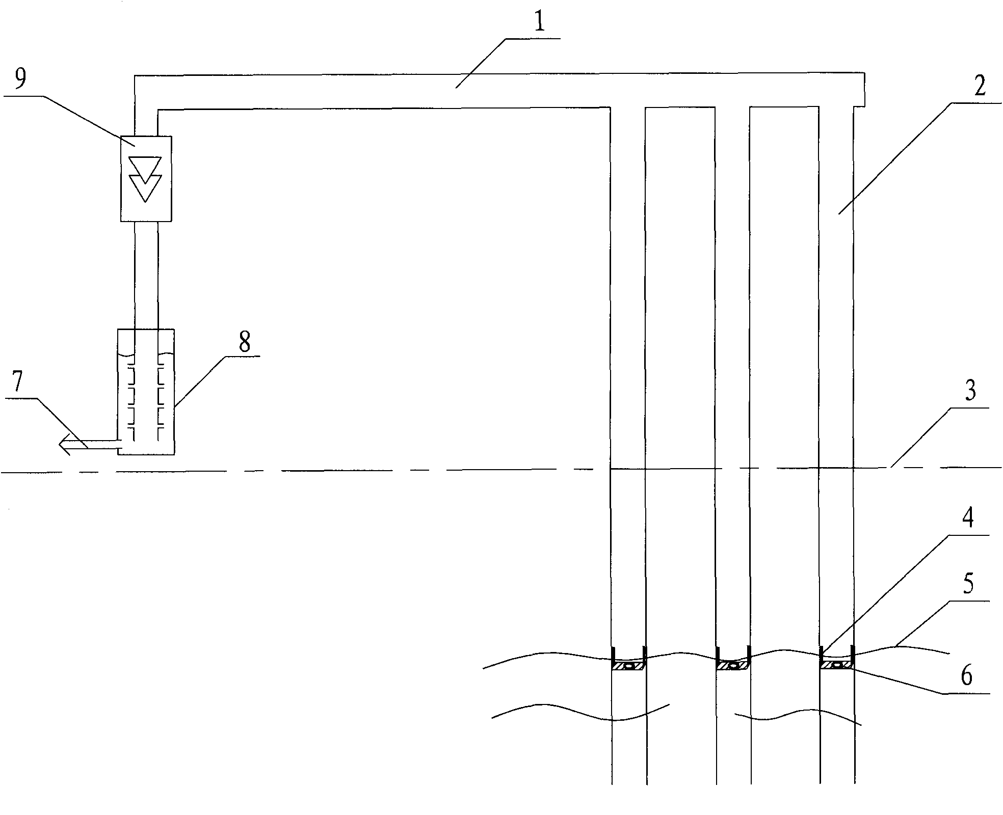
[0012] Such as figure 1 As shown, the main structure of the present invention includes a main pipeline 1, a compression pump 9 and a hot water converter 8 with a hot water outlet 7. A compression pump 9 is connected in series on the main pipeline 1, and the outlet of the compression pump 9 is connected to A hot water converter 8 with a hot water outlet 7, the main pipe is also provided with uniformly distributed heat-absorbing branch pipes 2 in parallel, the water inlet end of the heat-absorbing branch pipes is arranged on the lower side of the groundwater level line 5, and the heat-absorbing branch pipes An ultrasonic generator 6 with a float 4 is provided to be suspended under the groundwater level, and the float can ensure that the ultrasonic generator 6 is always in the best working position when the groundwater level changes. Above-mentioned ultrasonic generator 6 that has float 4 can be replaced with the water mist stirring pump that has float.

[0013] During installat...

Embodiment 2

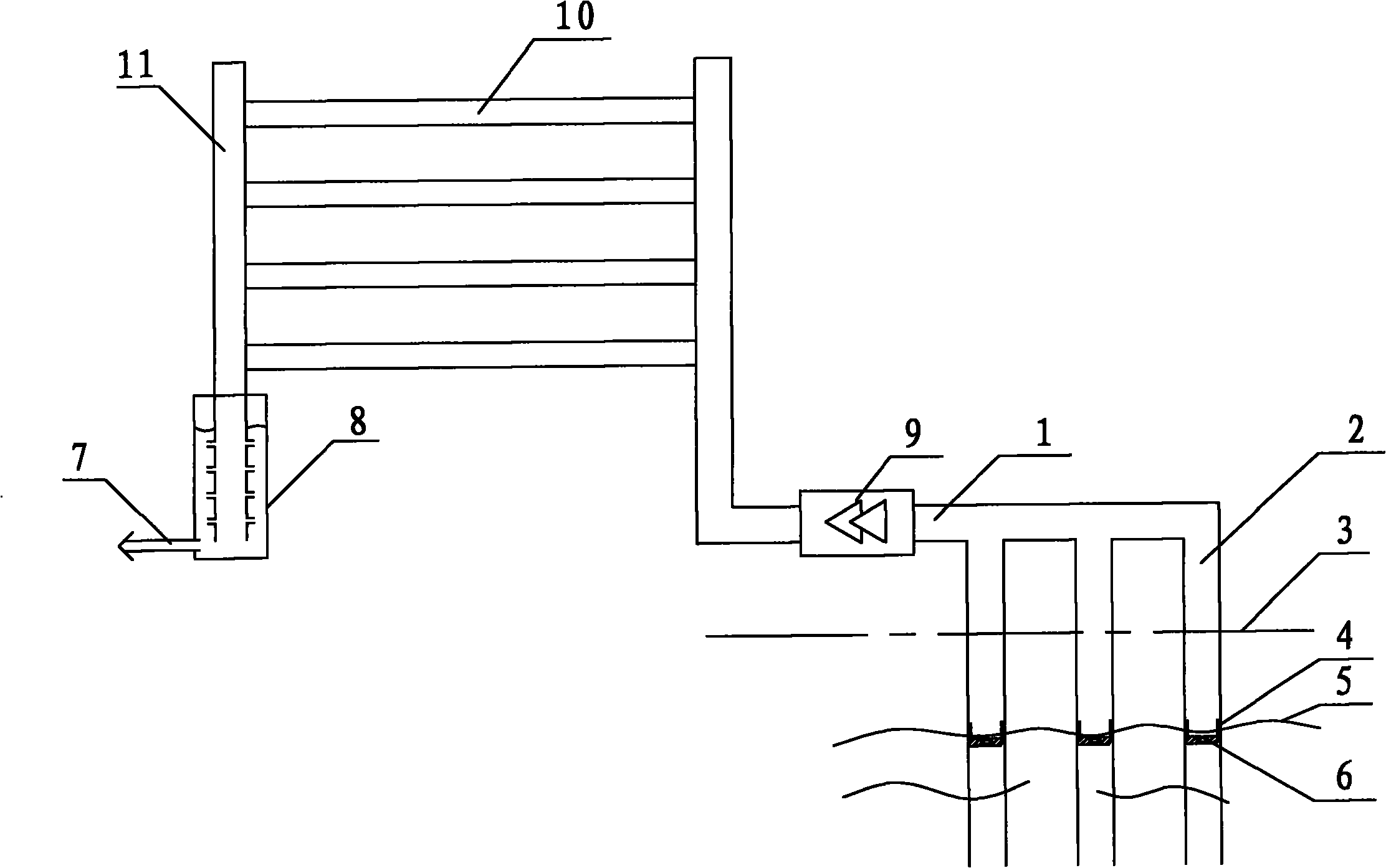
[0015] Such as figure 2 As shown, the main structure of the present invention includes a main line pipeline 1, a compression pump 9 and a hot water converter 8 with a hot water outlet 7. A compression pump 9 is connected in series on the main line pipeline 1, and between the main line pipeline and the output pipeline 11 Heat release branch pipes 10 are evenly distributed in parallel, and the outlet of the output pipe 11 is connected to a hot water converter 8 with a hot water outlet 7 . On the main pipeline, there are evenly distributed heat-absorbing branch pipes 2 arranged in parallel. Above-mentioned ultrasonic generator 6 that has float 4 can be replaced with the water mist stirring pump that has float.

[0016] The difference between this embodiment and Embodiment 1 is that when the water mist generated by the ultrasonic generator energizes gradually absorbs heat and becomes superheated steam and passes through the outlet of the compression pump 9, the superheated steam...

example 3

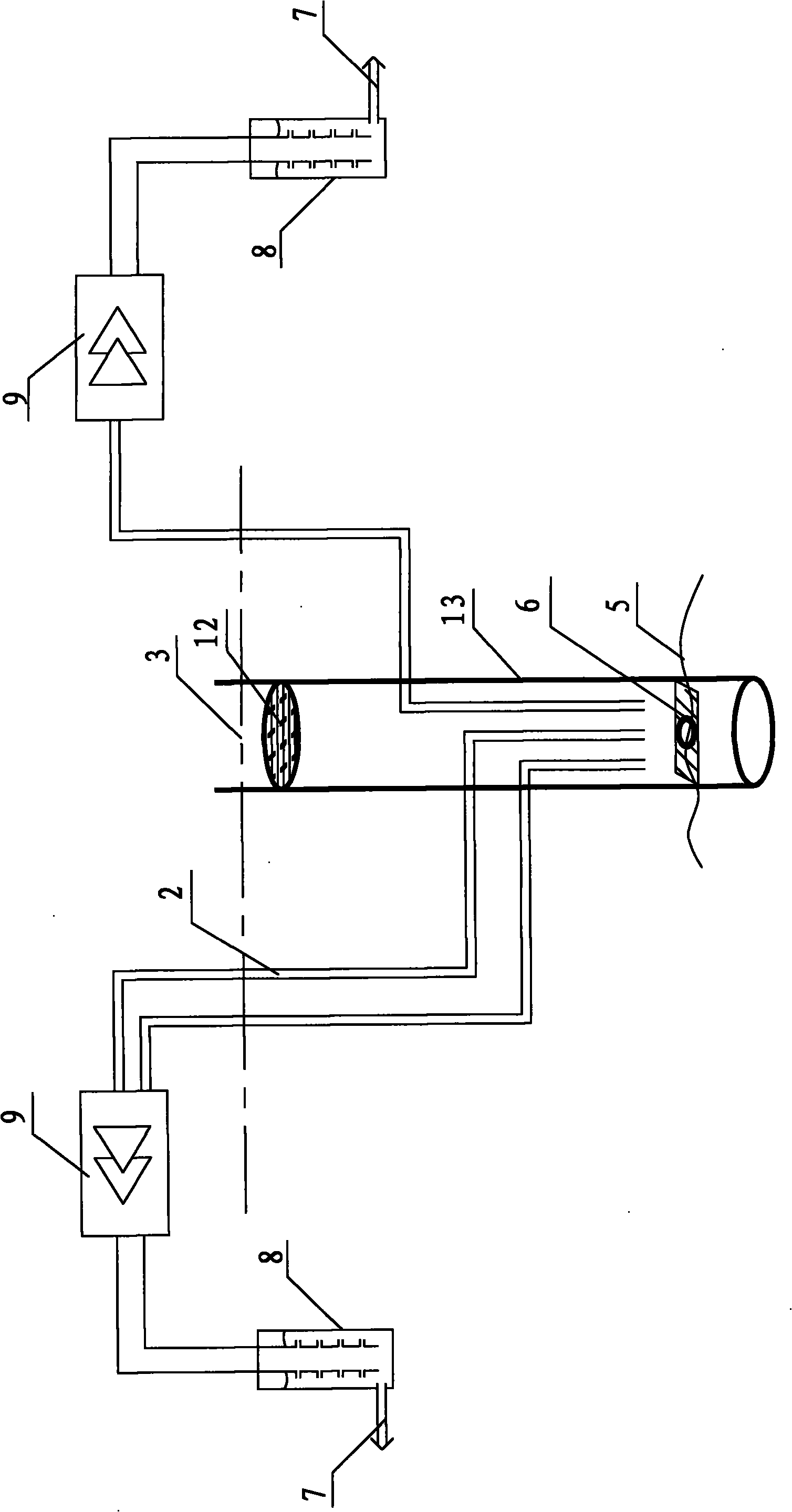
[0018] Such as image 3 As shown, the main structure of the present invention includes two compression pumps 9 and a hot water converter 8 with a hot water outlet 7, each compression pump is connected with a heat-absorbing branch pipe 2, and the intake end of the heat-absorbing branch pipe is arranged on On the upper side of the underground water level line 5 of the underground well 13, an ultrasonic generator 6 is arranged in the underground well. The above-mentioned ultrasonic generator 6 can be replaced by a water mist stirring pump. Also include well cover 12 among the figure.

[0019] This example can provide heat for multiple users. The principle of atomized water mist in the well entering the heat-absorbing branch pipe to absorb heat and finally turning into superheated steam is the same as Example 1, except that each user has a set of the same equipment.


PUM


Abstract

The invention relates to a water-ground-source heat pump system, comprising a main line pipeline, a compressor pump and a hot water converter with a hot water outlet. The technical points are that the compressor pump is connected in series on the main line pipeline; the outlet of the compressor pump is connected with the hot water converter with the hot water outlet; the main line pipeline is also provided with uniformly distributed heat-absorption branch pipes in a parallel manner; the water inlet end of each heat-absorption branch pipe is arranged at the lower side of a groundwater table; and an ultrasonic generator or a water mist agitator pump is arranged in the heat-absorption branch pipe. The invention is characterized in that the invention utilizes a radiation principle of energy to firstly turn water into the water mist at normal temperature with the ultrasonic generator, transform the water mist to superheated steam through absorbing heat by the water mist, and raise the temperature of water in the hot water converter at last, and the obtained hot water after heating can be used for domestic hot water. The invention has the advantages of high heat exchange rate, uneasy scaled system, convenient maintenance, simple whole structure, low production cost and long service life of the device.

Description

technical field [0001] The invention belongs to the technical field of heat pumps, in particular to a water and ground source heat pump system for efficiently recovering and utilizing low-grade heat energy. Background technique [0002] As we all know, with the rapid economic growth of the world's population, energy consumption has increased dramatically. Today, with increasingly severe environmental pollution and increasingly endangered living environment, people's desire to be green and protect the environment is becoming increasingly strong. In recent years, human beings have been exploring and researching the use of renewable energy. Although we have discovered new energy sources such as solar energy, nuclear fusion energy, biomass energy, wind energy, water conservancy energy, wave energy, tidal energy, and underground thermal energy, due to These energies are low-grade energies, and the development and utilization of these energies require different technologies and e...

Claims


Application Information

Patent Timeline
IPC IPC(8): F24H4/02F25B30/06F24D3/18F24D3/08
CPCY02B30/12Y02B10/40
Inventor 奉政一
Owner 奉政一
Why Eureka
Try Eureka