Strong and weak current composite cable and manufacturing method thereof
A composite cable and manufacturing method technology, applied in cable/conductor manufacturing, insulated cables, cables, etc., can solve the problems of wasting materials, power space labor, unfavorable for laying, management, and finished product assembly, etc. Conducive to installation and laying, the effect of small error
- Summary
- Abstract
- Description
- Claims
- Application Information
AI Technical Summary
Problems solved by technology
Method used
Image
Examples
Embodiment 1
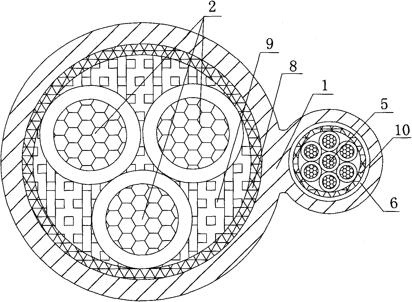
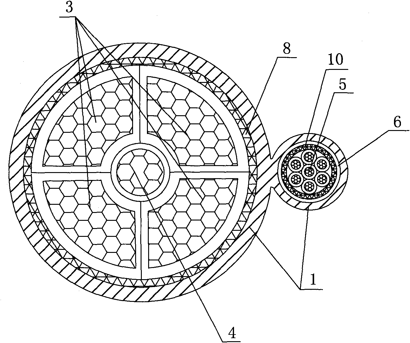
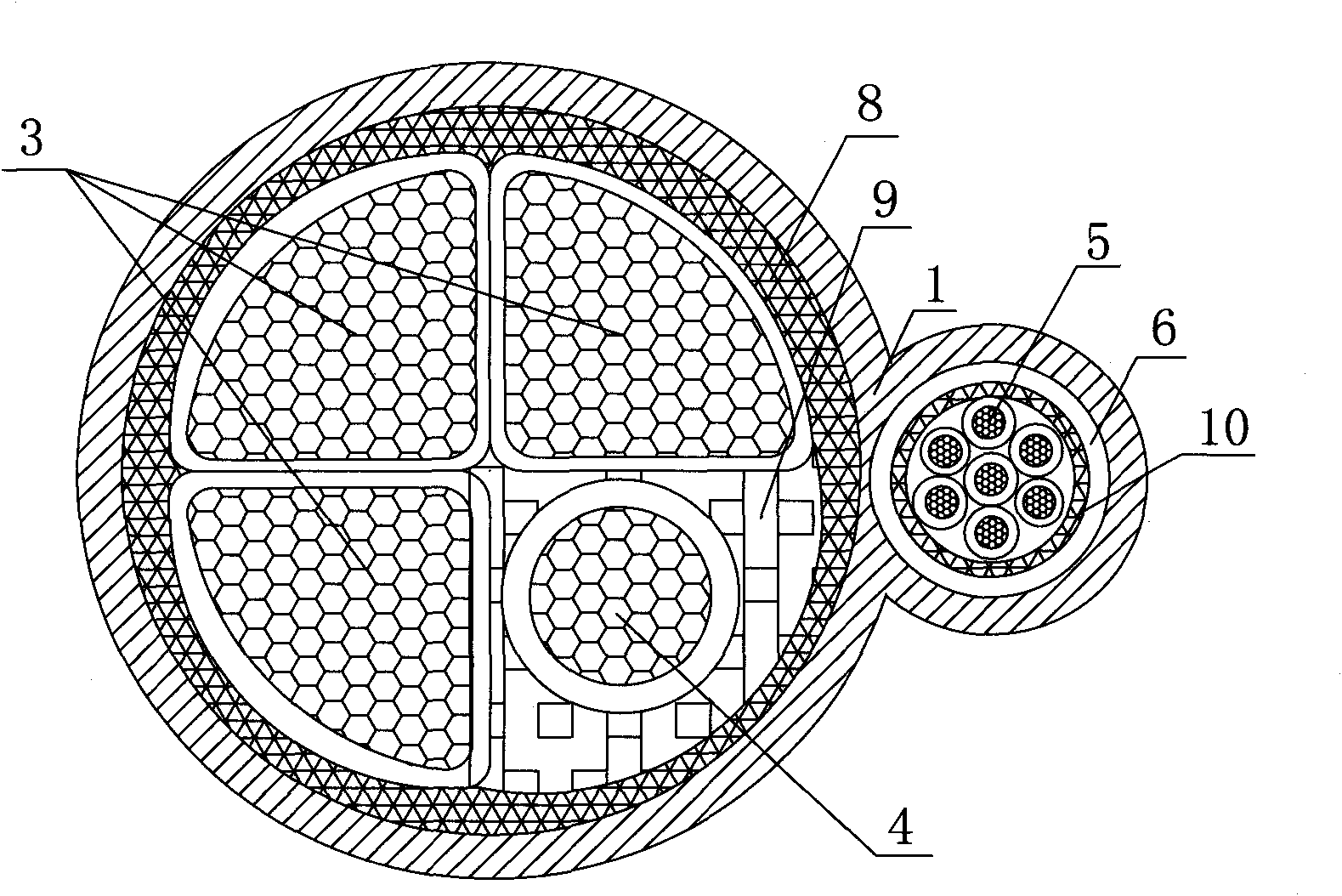
[0024] Embodiment 1: as Figure 1 to Figure 3 As shown, a strong and weak current composite cable according to the present invention includes a power cable, a control cable and an outer sheath 1, and the power cable and the control cable are arranged in the same outer sheath 1; the power cable includes one or more Root nominal section is 10mm 2 ~300mm 2 2 circular insulated wire cores, or multiple wires with a nominal cross-section of 10mm 2 ~300mm 2 The fan-shaped or tile-shaped insulated core 3 with a nominal cross-section of 6mm 2 ~150mm 2 The core combination formed by the circular insulated core 4; the control cable includes a nominal cross-section of 0.5mm 2 ~10mm 2 The control insulated wire core 5 is covered with a shield 6 outside the control insulated wire core 5 . In the present invention, the outer sheath 1 is preferably a double-hole outer sheath, and the power cable and the control cable are arranged in the corresponding holes. The cores of different shap...
Embodiment 2
[0030] Embodiment 2: a kind of preparation Figure 1 to Figure 3 The method for the strong and weak current composite cable shown, the method comprises the following steps:
[0031] The first step is to prepare power cables and control cables respectively:
[0032] A plurality of copper wires are first twisted into inner conductors of corresponding shapes according to the design requirements of power cables, and then the outer surfaces of the inner conductors are extruded and insulated to form cores of corresponding shapes. When there is one core, it is a power cable and directly enters The second step: when there are multiple wire cores, tie the multiple wire cores together with a tape, and fill the filler between the tape and the wire cores and between each wire core to make a power cable;
[0033] A plurality of copper wires are first made into a solid conductor according to the design requirements of the control cable, and the insulation is extruded on the outside of the ...
Embodiment 3
[0036] Embodiment 3: as Figure 4As shown, the specification prepared by this embodiment is FH-D / K-YJV / VV-0.6 / 1KV (FH represents composite, D / K represents power / control, YJV / VV represents the conventional expression method of insulating sheath, 0.6 / 1KV means the voltage level) 3×70+1×35 / 7×1.5 (3×70+1×35 / 7×1.5 means 3 fan-shaped insulated cores, and the nominal cross-sectional area of each fan-shaped insulated core is 70mm 2 , a nominal cross-sectional area of 35mm 2 Circular insulated wire cores, 7 control insulated wire cores, the nominal cross-sectional area of each control insulated wire core is 1.5mm 2 ,) the strong and weak current composite cable to elaborate the manufacturing method of strong and weak current composite cable, the concrete steps of this method are:
[0037] The first step is to prepare power cables and control cables respectively:
[0038] 1) Wire drawing: select Φ8.0mm electrolytic copper rod, draw the Φ8.0mm electrolytic copper rod to Φ2.52mm...
PUM
| Property | Measurement | Unit |
|---|---|---|
| Section | aaaaa | aaaaa |
Abstract
Description
Claims
Application Information
 - R&D
- Intellectual Property
- Life Sciences
- Materials
- Tech Scout
- Unparalleled Data Quality
- Higher Quality Content
- 60% Fewer Hallucinations
Browse by: Latest US Patents, China's latest patents, Technical Efficacy Thesaurus, Application Domain, Technology Topic, Popular Technical Reports.
© 2025 PatSnap. All rights reserved.Legal|Privacy policy|Modern Slavery Act Transparency Statement|Sitemap|About US| Contact US: help@patsnap.com


