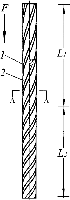
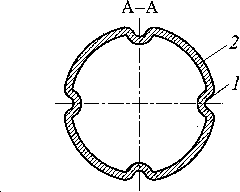
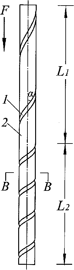
Field synergy effect-based cracking furnace tube
A cracking furnace tube and field synergy technology, applied in cracking, non-catalytic thermal cracking, petroleum industry and other directions, can solve the problems of shortening the coke cleaning cycle, increasing the flow resistance in the tube, occupying the effective volume, etc., to reduce heat transfer resistance, The effect of reducing coking and reducing heat transfer resistance
- Summary
- Abstract
- Description
- Claims
- Application Information
AI Technical Summary
Problems solved by technology
Method used
Image

Examples
Embodiment
[0035] According to the technical principle of the present invention, the ethylene cracking experiment test was carried out, and the comparison test was carried out with the smooth circular tube in the same cracking furnace and under the same operating conditions, and the outlet temperature, ethylene yield and pressure drop in the tube were measured experimentally. The operating conditions are shown in Table 1, and the test results are shown in Table 2 and Table 3.
[0036] Table 1 Test operating conditions
[0037]
[0038]
[0039] Table 2 Test result 1 (initial stage of operation)
[0040] project
Furnace tube of the present invention
Furnace tube of the present invention
Smooth round tube
Tube surface temperature
990℃
925℃
1015℃
[0041] project
Furnace tube of the present invention
Furnace tube of the present invention
Smooth round tube
output temperature
855℃
809℃
812℃
...
PUM
| Property | Measurement | Unit |
|---|---|---|
| thermal resistance | aaaaa | aaaaa |
Abstract
Description
Claims
Application Information
 - R&D
- Intellectual Property
- Life Sciences
- Materials
- Tech Scout
- Unparalleled Data Quality
- Higher Quality Content
- 60% Fewer Hallucinations
Browse by: Latest US Patents, China's latest patents, Technical Efficacy Thesaurus, Application Domain, Technology Topic, Popular Technical Reports.
© 2025 PatSnap. All rights reserved.Legal|Privacy policy|Modern Slavery Act Transparency Statement|Sitemap|About US| Contact US: help@patsnap.com