
Method for achieving water-injecting high-pressure combustion through pipeline of fuel nozzle

A combustion method and oil nozzle technology, which are used in burners, earth-moving drilling, and fluid production, etc., can solve the problems of shortened service life (sometimes less than one working day of gas injection, prone to bursting, denudation, difficult practical application, etc.) Achieve the effect of prolonging the continuous working cycle, improving work stability and improving reliability

Inactive Publication Date: 2010-09-08
SOUTHEAST UNIV
View PDF7 Cites 8 Cited by
  • Summary
  • Abstract
  • Description
  • Claims
  • Application Information

AI Technical Summary

Problems solved by technology

However, these patented devices still have deficiencies in structural design, which brings many difficulties to practical applications.
Typically: the temperature in the combustion chamber is too high (about 2000°C), and under the condition of high oil well back pressure (as is usually the case in practice), ① the high temperature center of the flame in the combustion chamber gradually moves to the fire-facing surface of the head, and the head The parts are easily burned (such as the end face of the fire, the ignition head of the igniter, the atomizer of the oil nozzle, etc.); The use effect of the lining is significantly reduced, thus greatly shortening the service life of the burner (or gas injector) (sometimes less than one gas injection working day)
And so on, the reliability and economy of the operation of the gas injection device will be seriously affected

Method used


Image

  • Method for achieving water-injecting high-pressure combustion through pipeline of fuel nozzle
  • Method for achieving water-injecting high-pressure combustion through pipeline of fuel nozzle
  • Method for achieving water-injecting high-pressure combustion through pipeline of fuel nozzle

Examples


Embodiment Construction

[0021] The present invention will be further described below in conjunction with the accompanying drawings.

[0022] The purpose of the present invention is to provide a new method for the oil thermal recovery gas injection high-pressure mixed gas generating device, which can create a reliable, easy-to-operate, long service life (main components can be continuous) for the recovery of oil, especially heavy oil. Work 8000 hours), energy-saving and efficient alternative new technology.

[0023] The device uses diesel oil, crude oil, natural gas or liquefied petroleum gas and compressed air to produce high-temperature and high-pressure flue gas mixed with water, thereby producing temperature and humidity that can be adjusted according to requirements, mainly composed of N2, CO2, water vapor (H2O) of the gas mixture. The mixed gas generating device is mainly used in the thermal exploitation of petroleum. The mixed gas generated by the mixed gas generating device can be directly in...


PUM


Abstract

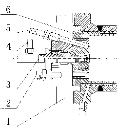
The invention relates to a method for achieving the water-injecting high-pressure combustion through the pipeline of a fuel nozzle. Fuel is allowed to enter a combustion chamber (10) from a fuel nozzle (3); compressed air is allowed to enter the combustion chamber (10) from an air distributor (2); a certain amount of water from a water injection hole (4) is injected into the combustion chamber (10) from the fuel nozzle (3) via the pipeline of the fuel nozzle, so that the operating temperature in the combustion chamber (10) can be reduced from approximate 2,000 DEG C to 1,500-1,600 DEG C; the operating end of an igniter (5) is led to the combustion chamber (10), so that the fuel and air can be ignited by the igniter (5) after the fuel and air entering the combustion chamber (10) are atomized and mixed; and high-temperature and high-pressure flue gas can be generated after the complete combustion. By injecting a certain amount of water into the water injection hole (4) on the pipeline of fuel, part of combustion heat can be absorbed by the water, thus stabilizing the operating temperature in the combustion chamber (10) at 1,500 to 1,600 DEG C. Therefore, the method of the invention has the advantages of high reliability and easy operation and significantly prolongs the service life of the equipment.

Description

technical field [0001] The invention relates to a method for a high-pressure mixed gas generating device used in petroleum thermal exploitation, and belongs to the technical field of petroleum exploitation equipment. Background technique [0002] The oil extraction process can be roughly divided into primary oil recovery, secondary oil recovery and multiple oil recovery. Steam recovery is a typical multiple oil recovery process. Steam oil recovery uses the heating effect of thermal energy to reduce the viscosity of crude oil, and at the same time increase the pressure of the oil layer to a certain extent, thereby improving the oil recovery rate of the oil well. [0003] Since the early 1980s, the practice of using steam thermal recovery technology in my country's oilfields has shown that this technology is more suitable for the low production cycle range of oil layers in formations above 800m. During the production process, the formation pressure continues to drop. After 6...

Claims


Application Information

Patent Timeline
Patent Type & Authority Applications(China)
IPC IPC(8): F23D11/00E21B43/24
Inventor 鲁维加郭宏伟
Owner SOUTHEAST UNIV
Learn More