

Bio-safety disposal method for dispelling dichlorodifluoromethane by induction heating and pyrolysis induction heating furnace
An induction heating furnace, a technology of harmless treatment, applied in chemical instruments and methods, separation methods, lighting and heating equipment, etc., can solve problems such as hidden safety hazards, increased processing costs, and difficulty in popularization and application, and achieve convenient start-up and operation. , The effect of high energy utilization rate and low power consumption
Active Publication Date: 2010-09-15
TIANJIN HEJIA VEOLIA ENVIRONMENTAL SERVICES
View PDF8 Cites 13 Cited by
- Summary
- Abstract
- Description
- Claims
- Application Information
AI Technical Summary
Problems solved by technology
However, there are various problems. For pyrolysis by combustion method, there are potential safety hazards due to the flammable gas in the mixed gas. At the same time, it increases the treatment cost and easily forms secondary pollutants.
Published patent CN1049295A has described a kind of method that freon is catalytically decomposed, uses the catalyst that comprises alumina or alumina-silicon dioxide composite oxide in this method, and decomposes freon under the condition that water vapor exists, but this The problem with this method is that the hydrogen fluoride produced by the decomposition of freon has a strong fluorination effect on alumina, which leads to the deactivation of the catalyst in a short time
Other methods are difficult to popularize and apply due to the limitation of equipment technology and cost
Method used
View moreImage
Smart ImageViewing Examples


Examples
Embodiment 1
Embodiment 2
Embodiment 3
Login to View More PUM
| Property | Measurement | Unit |
|---|---|---|
| Melting point | aaaaa | aaaaa |
| Diameter | aaaaa | aaaaa |
| Length | aaaaa | aaaaa |
Abstract
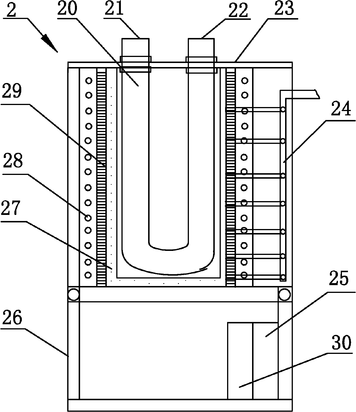
The invention relates to a bio-safety disposal method for dispelling dichlorodifluoromethane by induction heating and a pyrolysis induction heating furnace. The method is characterized by comprising steps of carrying out pyrolytic reaction on a preheated feed gas which is a mixed gas of dichlorodifluoromethane, steam and air in a high-temperature environment generated by induction heating and carrying out absorption and inversion on pyrolysis products, wherein the proportioning of the feed gas is as follows: the flow ratio of the steam to the dichlorodifluoromethane is shown in the specification, the flow ratio of the air to the dichlorodifluoromethane is shown in the specification, and in the formula, a, b and c are respectively the number of carbon, hydrogen and halogen atoms of one dichlorodifluoromethane molecule. The pyrolysis induction heating furnace is characterized in that a crucible in the traditional pyrolysis induction heating furnace is internally provided with an acid corrosion resistant and thermostability bending-shaped metal coiler, the supply frequency is 10-300kHz and the power is 10-50kW. The invention has the advantages of quick warming speed, little power consumption, high energy utilization rate and pyrolysis efficiency, convenient starting operation, good operation safety and easy scale realization.
Description
technical field The invention relates to a harmless treatment method and equipment for heating and digesting Freon, in particular to a harmless treatment method for induction heating and digestion of Freon and a pyrolysis induction heating furnace. Background technique Freons (CFCs) are composed of four elements, C, Cl, H, and F, and are mainly derivatives of methane and ethane. The scientific name is chlorofluorocarbons. It is chemically stable, non-flammable and non-toxic, and is widely used as a refrigerant, foaming agent and cleaning agent in household appliances, daily chemicals, automobiles, fire-fighting equipment and other fields. However, CFCs react with ozone in the stratosphere, continuously destroying ozone molecules, resulting in a large amount of depletion of the ozone layer, and ultimately bringing various hazards to human health and the ecological environment. At present, there are three main ways to solve the problem of CFCs damaging the environment: ① red...
Claims
Login to View More Application Information
Patent Timeline
 IPC IPC(8): B01D53/76B01D53/78B01D53/70F27B14/08
Inventor孙贻超卢学强邓小文马建立邵晓龙刘红磊袁敏王哲张艳华
OwnerTIANJIN HEJIA VEOLIA ENVIRONMENTAL SERVICES