Plastic optical fiber bus optical information coupling device

A coupling device and plastic optical fiber technology, which is applied in optical fiber transmission, electromagnetic wave transmission system, comprehensive factory control, etc., can solve the problems of too late to adopt, and can not quickly predict the gas concentration, so as to reduce the cost of hardware and software, reduce the cost of software development, The effect of widening utilization

Inactive Publication Date: 2010-09-15
HARBIN ENG UNIV
View PDF3 Cites 2 Cited by
  • Summary
  • Abstract
  • Description
  • Claims
  • Application Information

AI Technical Summary

Problems solved by technology

At present, whether it is a gas sensor or a gas monitoring system, the gas concentration provided is only the current local safety status data, and it is impossible to quickly predict the future gas concentration in a wide area. As a result, when the gas concentration exceeds the limit, it is too late to take effective precautions measure

Method used


Image

  • Plastic optical fiber bus optical information coupling device
  • Plastic optical fiber bus optical information coupling device
  • Plastic optical fiber bus optical information coupling device

Examples


example 1

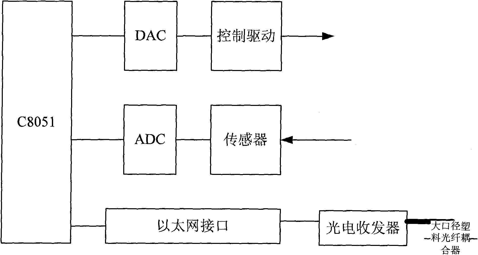
[0032] Example 1: A landslide monitoring system is formed by using a plastic optical fiber bus optical information coupler.

[0033] The monitoring bus system of the landslide monitoring system has various detection nodes that can perform network expansion (location by IP address), such as stress measurement nodes, strain-type deformation detection nodes, mountain vibration information collection nodes, and optical interference mountain deformation information collection nodes; GPS mountain Deformation information collection and processing nodes, etc. The sensor information transmitted by each light is coupled into the measurement and control bus system using a distributed optical fiber network through a large-diameter plastic optical fiber. Due to the plastic optical fiber coupler, the embedded sensor of the optical fiber bus can be connected without cables and the optical fiber signal transmission bandwidth is strong. Through the measurement and control terminal of the distr...

example 2

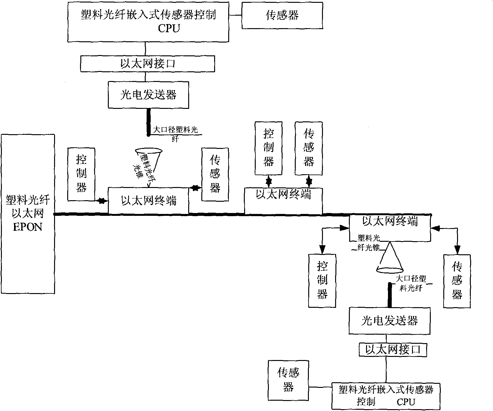
[0034] Example 2: A landslide monitoring system is constructed using plastic optical fiber bus embedded sensors.

[0035] (1 Overview

[0036] According to its functions, the monitoring bus system of the landslide monitoring system has detection nodes that can expand the network (locate through IP addresses), such as stress measurement nodes, deformation detection nodes, mountain deformation image information collection nodes, and optical interference mountain deformation information collection nodes. ; GPS mountain deformation information acquisition and processing node. The sensor information transmitted by each light is coupled into a distributed measurement and control bus system based on a single-mode optical fiber network through a large-diameter plastic optical fiber. Since the plastic optical fiber bus embedded sensor has no cable connection and the optical fiber signal transmission bandwidth is strong, through the measurement and control terminal of the distributed m...


PUM


Abstract

The invention discloses a plastic optical fiber bus optical information coupling device, which is characterized in that: a terminal computer C8051 performs information collection through an ADC module; a wireless transceiver module and a laser transceiver module are used to perform communication through multi-spectrum wireless electrooptical signals and an optical network to send measurement information to a control center; the wireless transceiver module and the laser transceiver module are used to perform communication through multi-spectrum wireless electrooptical signals and the optical network to send the control information of the control center to the terminal computer C8051; and the terminal computer C8051 inputs the information through the DAC module into the controller to perform control. The device of the invention can overcome the drawbacks of information coupling singleness and immobility of the conventional terminal, increase network information exchange performance, enable a bus to measure and control through different kinds of media information, and form a mobile network measurement and control bus.

Description

technical field [0001] The invention relates to an automation device, in particular to an industrial control optical fiber network information device in the field of automation. Background technique [0002] The information coupling between industrial control sensors and control buses in my country is almost all electronic technology, which has disadvantages such as complex use, large mutual interference, poor work stability, frequent information format conversion, and few types of information coupling, which seriously restricts industrial networked measurement and control buses. The effective reception of sensor information and the network transmission of control information. For example, according to the investigation of the causes of coal mine gas explosions by my country's coal mine safety production supervision department, gas explosions are in many cases caused by sudden large amounts of gas gushing out. At present, whether it is a gas sensor or a gas monitoring system...

Claims


Application Information

Patent Timeline
Patent Type & Authority Applications(China)
IPC IPC(8): G05B19/418H04B10/12H04B10/25
CPCY02P90/02
Inventor 王克家王怡
Owner HARBIN ENG UNIV
Why Eureka
Try Eureka