Device and method for mounting optical glass under vision guide

A technology of optical glass and installation method, which is applied in nuclear reactors, nuclear power generation, climate sustainability, etc., can solve problems such as inability to guarantee installation accuracy, easy pollution of optical glass, damage to optical components, etc., to improve reliability and safety, The effect of avoiding accidental injury and improving production efficiency

Active Publication Date: 2010-09-22
INST OF AUTOMATION CHINESE ACAD OF SCI
View PDF4 Cites 33 Cited by
  • Summary
  • Abstract
  • Description
  • Claims
  • Application Information

AI Technical Summary

Problems solved by technology

[0005] In order to solve the problem that the existing optical glass installation system has low efficiency during handling and installation, and is very easy to pollute the optical glass or even

Method used


Image

  • Device and method for mounting optical glass under vision guide
  • Device and method for mounting optical glass under vision guide
  • Device and method for mounting optical glass under vision guide

Examples


Embodiment Construction

[0043] The specific implementation of the present invention will be described in detail below in conjunction with the accompanying drawings.

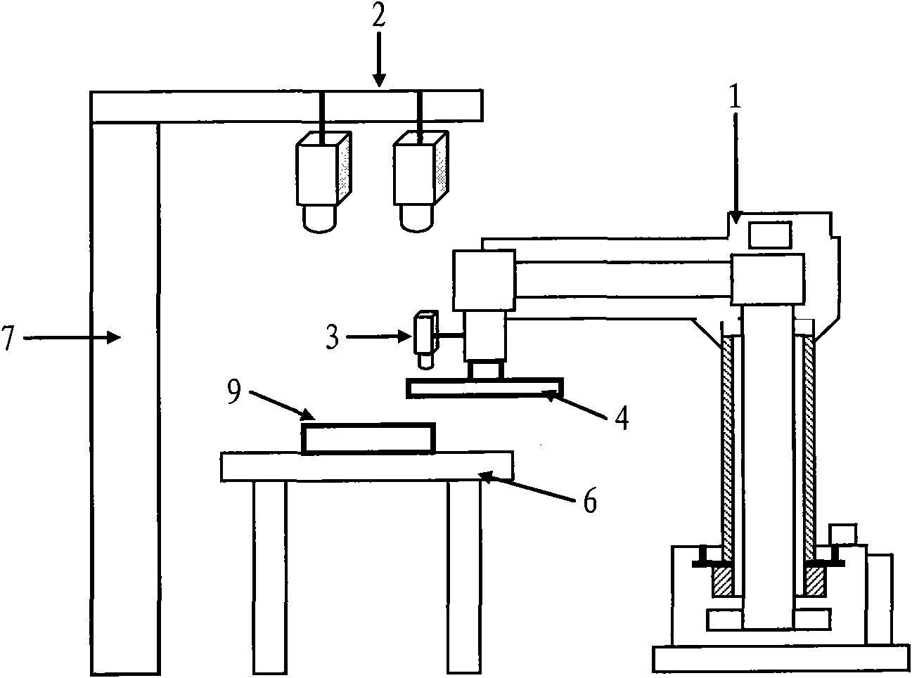
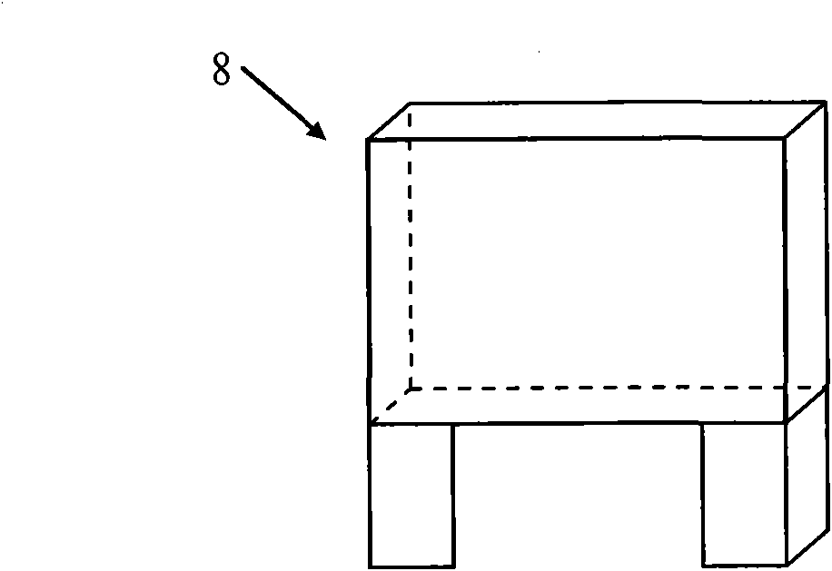
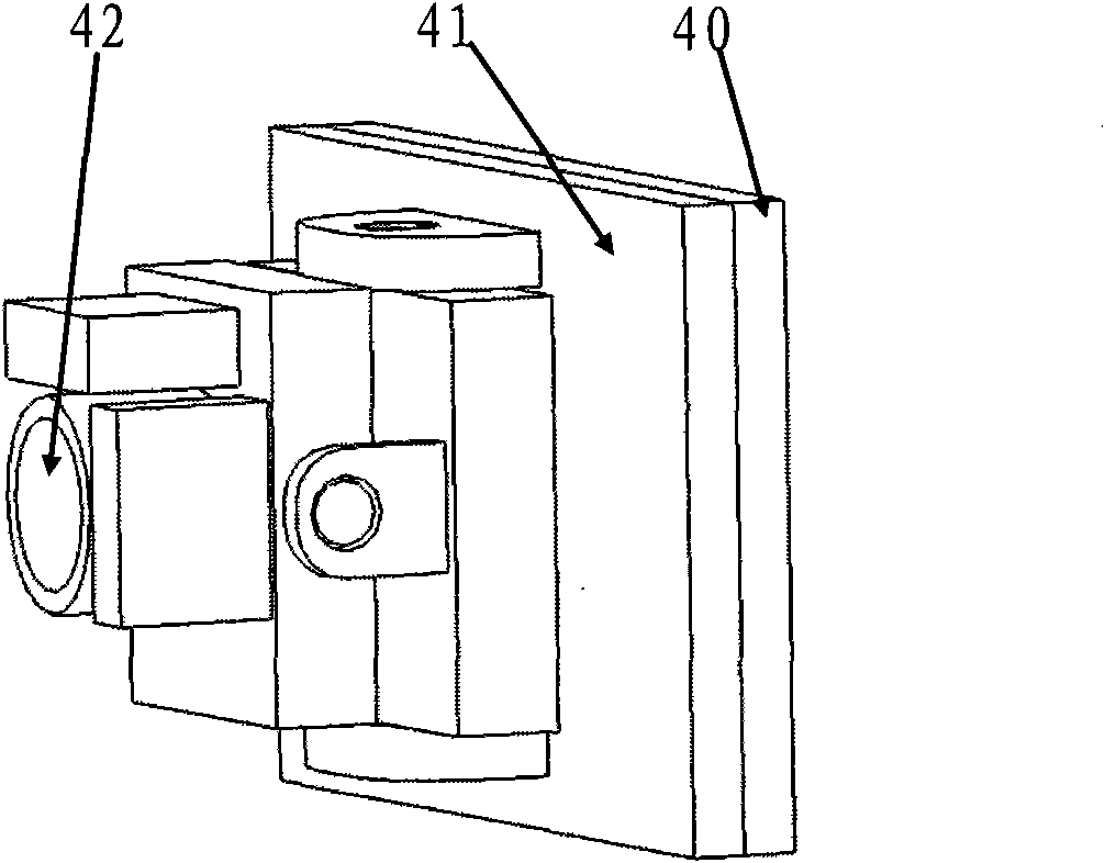
[0044] Such as figure 1 It shows a large-scale optical glass installation device based on an industrial robot under visual guidance, including an industrial robot 1, an upper visual recognition unit 2, a front-end visual positioning unit 3, a grabbing device 4, a control cabinet 5, a workbench 6, a bracket 7, and a glass frame 8 , Optical glass 9. The upper visual recognition unit 2 is installed on the horizontal end of the support 7 and is located above the workbench 6. The horizontal end of the support 7 is parallel to the work surface of the workbench 6, and is used to collect images of the optical glass 9 on the workbench 6 and identify the optical glass 9. The rough position of the apex of the glass 9; the front-end visual positioning unit 3 is installed on the arm of the industrial robot 1 and is positioned above the workbench 6,...


PUM


Abstract

The invention relates to a method and a device for mounting optical glass under vision guide. The method comprises the following steps of: acquiring images of the optical glass on a workbench at the same time by adopting two cameras arranged above the workbench; calculating a rough position of the vertex of the optical glass by adopting two sets of image processing algorithms in a computer respectively; acquiring the image of the optical glass through a camera arranged at the tail end of an industrial robot, and calculating the central position and the azimuth of the optical glass in the computer by adopting the image processing algorithm; and contacting a gripping device and four edges of the optical glass by adopting four vacuum sucking strips, adsorbing the optical glass from the workbench through an adsorption force, and placing the optical glass into a glass framework. The device comprises the industrial robot, an upper vision identifying unit, a front-end vision positioning unit and a control cabinet. The industrial robot faces the workbench on a zero-potential surface, and the glass framework is positioned on the rear side of the robot. The front-end vision camera can acquire the position of the glass framework.

Description

technical field [0001] The invention relates to an optical glass installation device and an installation method under visual guidance. Background technique [0002] The laser inertial confinement nuclear fusion experiment is one of the most cutting-edge research topics in the world. The experiment controls the laser amplification in stages, and finally forms a high-energy laser compression deuterium-tritium target implosion to achieve a controllable nuclear fusion reaction. In the laser inertial confinement fusion experiment, large optical glass is the working material and core material of the amplifier, which is mainly used in the main laser system as a power amplifier and multi-channel or main amplifier. Therefore, the installation quality of optical glass is crucial for laser systems and even fusion experiments. The quality of optical glass is relatively heavy (about 50 kg per piece), the cost is expensive, and it is required that no traces be left on the surface of the ...

Claims


Application Information

Patent Timeline
IPC IPC(8): G21B1/25
CPCY02E30/10
Inventor 苏建华乔红刘传凯
Owner INST OF AUTOMATION CHINESE ACAD OF SCI
Why Eureka
Try Eureka