Device and method for automatically detecting incident angle in elliptical polarization measuring system

A technology of incident angle and measurement system, applied in the field of optical measurement, can solve the problems of low cost, inability to record automatically by equipment, low efficiency, etc., and achieve the effect of low cost

Active Publication Date: 2010-09-29
北京量拓科技有限公司
View PDF2 Cites 19 Cited by
  • Summary
  • Abstract
  • Description
  • Claims
  • Application Information

AI Technical Summary

Problems solved by technology

However, there are many defects, such as: (a) it is easy to cause the angles of the polarizer arm and the analyzer arm to be inconsistent due to human adjustment errors or reading errors, and the analyzer arm may not receive the detection light; (b) it is easy to cause human errors , resulting in the inconsistency between the incident angle modeled in the computer and the actual probe light incident angle, leading to errors in data analysis results; (c) after each measurement, the incident angle value cannot be automatically recorded by the equipment, and manual recording is required, which is very inefficient , it is also easy to cause human error and affect the measurement results
(2) Use the photoelectric encoder to obtain the current angle of incidence and reflection. This method can realize the automation of measurement, but requires the photoelectric encoder to be strictly concentric with the center of rotation, and has high requirements for installation. On the other hand, the price of the photoelectric encoder Expensive, especially for ellipsometry systems that separate angles of incidence
(3) Do not use any angle detection, and rely on stepper motor pulse technology for open-loop control to obtain the incident angle. This method is low in cost, but there is a problem of motor out of step, which affects the measurement accuracy of the incident angle
It can be seen that in the ellipsometric measurement system, the current manual method, or the method of using a photoelectric encoder, or the method of open-loop stepping motor control is difficult to meet the requirements of low cost, fast, high efficiency, automation, and high reliability. Applications

Method used


Image

  • Device and method for automatically detecting incident angle in elliptical polarization measuring system
  • Device and method for automatically detecting incident angle in elliptical polarization measuring system
  • Device and method for automatically detecting incident angle in elliptical polarization measuring system

Examples


Embodiment 1

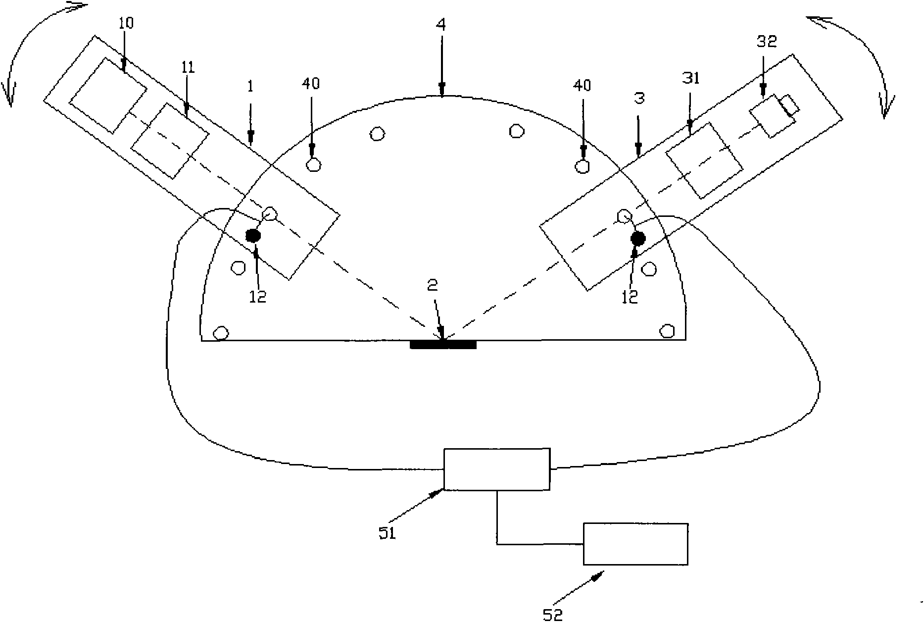
[0056] Such as figure 1 As shown, the schematic diagram shows a device for automatic detection of incident angle in an ellipsometry system (basic structure: polarizing arm, sample, analyzer arm, and substrate).

[0057] The structure of the system is as follows: a position detection switch 40 is installed on the substrate 4, a trigger device 12 is installed on the polarizing arm 1, and a trigger device 12 is also installed on the analyzer arm 3. When the deflection arm 1 and the analyzer arm 3 rotate to a certain angle, the trigger device 12 triggers the position detection switch 40 at that position, and the left and right sides output signals respectively. In order to determine whether the angle values ​​on both sides are consistent, the position detection switch 40 is electrically connected to the signal processing unit 51, and the signal processing unit 51 judges and processes the signal output by the position detection switch 40. The signal processing unit 51 is electrically ...

Embodiment 2

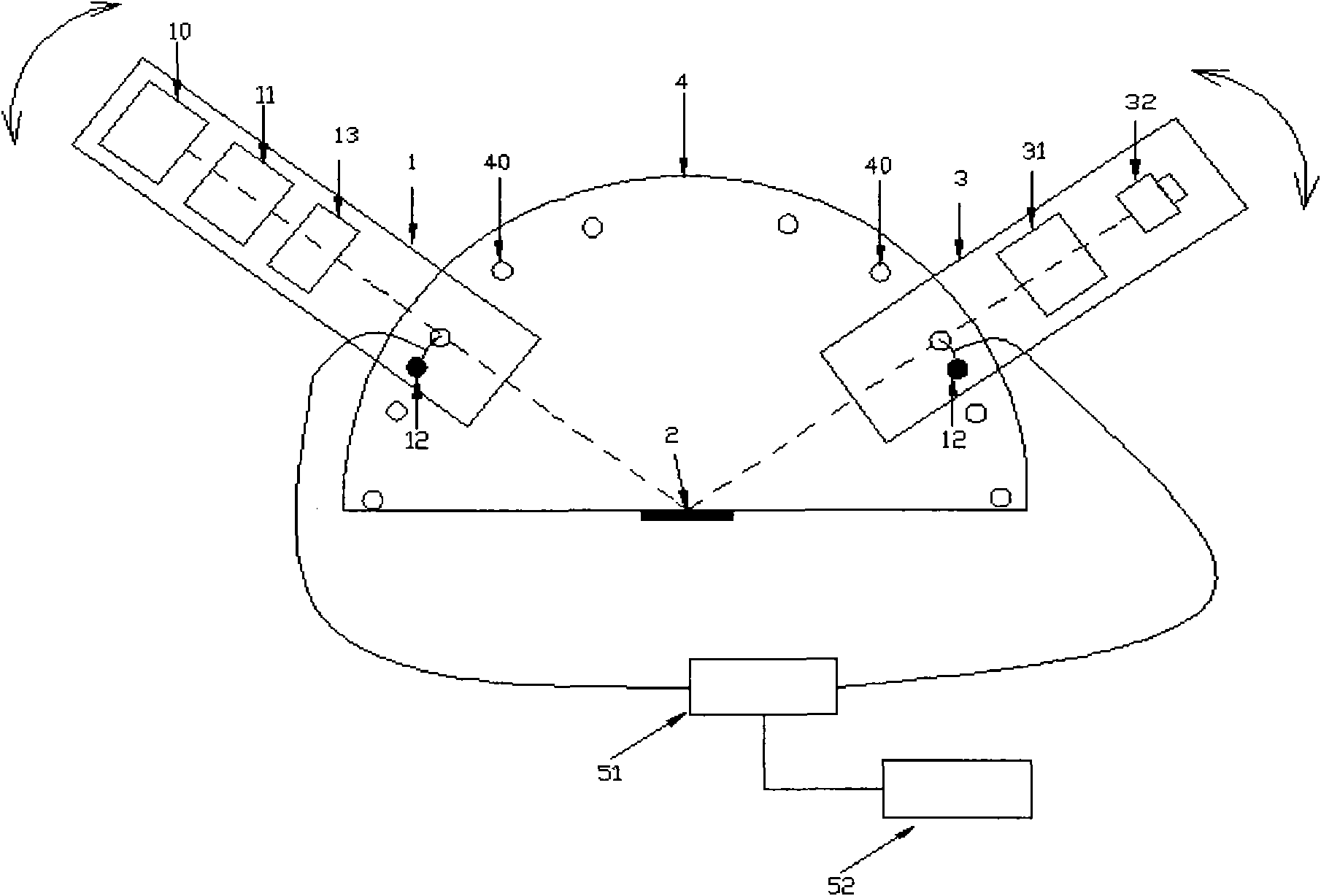
[0066] Such as figure 2 As shown, the schematic diagram shows a device for automatic detection of the incident angle in an ellipsometry system (basic structure: polarizing arm, sample, analyzer arm, and substrate).

[0067] In the above device, compared with the first embodiment, the difference is that the phase compensator 13 is installed between the linear polarizer 11 on the polarizing arm 1 and the sample 2, and the rest is the same as the device in the first embodiment.

[0068] In the above device, the phase compensator 13 can be a 1 / 4 glass slide or a glass slide with any phase retardation, which has two directions of fast axis and slow axis perpendicular to each other in a plane perpendicular to the propagation direction of light waves. , The phase delay difference of light waves in the two directions is different. The glass slide can be a mica glass slide, a liquid crystal with phase retardation, a quartz glass slide, a thin film glass slide, a total reflection type phase...

Embodiment 3

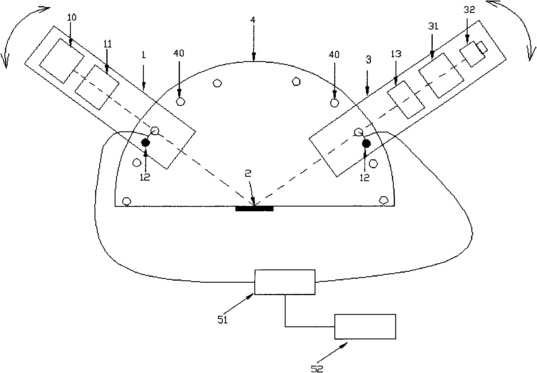
[0071] Such as image 3 As shown, the schematic diagram shows a device for automatic detection of the incident angle in an ellipsometry system (basic structure: polarizing arm, sample, analyzer arm, and substrate).

[0072] In the above device, except that the phase compensator 13 is installed between the linear polarizer 11 on the analyzer arm 3 and the sample 2, the other is the same as the device in Example 2.

[0073] In the above device, when the incident angle in the ellipsometry device needs to be automatically detected, the same method steps as in the second embodiment are used.


PUM


Abstract

The invention discloses a device for automatically detecting an incident angle in an elliptical polarization measuring system, which comprises a polarizing arm, a polarization detection arm and a substrate. The polarizing arm is used for producing detection light waves in a polarization state and emitting the detection light waves onto a sample; the polarization detection arm is used for performing polarization state re-modulation on the light waves reflected by the sample and detecting light energy; the substrate is used for supporting the polarizing arm and the polarization detection arm and is provided with a plurality of position detection switches; both the polarizing arm and the polarization detection arm are provided with triggering devices for triggering the position detection switches; and when the polarizing arm and the polarization detection arm rotate to different positions, the triggering device arranged on the polarizing arm and the polarization detection arm change the states of the position detection switches to obtain an incident angle signal and a reflecting angle signal so as to realize position detections of the polarizing arm and the polarization detection arm and automatic detection of the incident angle. The device and a method for automatically detecting the incident angle in the elliptical polarization measuring system provided by the invention have the advantages of simple structure, easy implementation, low cost, rapidness, high efficiency, automation and high reliability.

Description

Technical field [0001] The invention relates to the field of optical measurement, in particular to a device and method for automatic detection of incident angle in an ellipsometric measurement system. Background technique [0002] Ellipsometry is one of the important means to characterize nano-films. It uses the changes in the polarization state of the detection light wave when reflected on the surface to detect the information of the sample (eg, refractive index n, extinction coefficient k, thickness of nano-film, surface roughness , Material electronic vibration information, etc.). The advantages of this technology are: (1) No disturbance or destructiveness to the sample during measurement, so it can be measured in real time, in vitro or even in vivo; (2) Sensitivity can reach atomic level analysis level, so it can The nano-film can detect with high sensitivity; (3) There are almost no restrictions on sample materials, which can be suitable for insulators, conductors, and semi...

Claims


Application Information

Patent Timeline
Patent Type & Authority Applications(China)
IPC IPC(8): G01N21/21
Inventor 孟永宏杨涛
Owner 北京量拓科技有限公司
Why Eureka
Try Eureka