
Purification method of industrial tail gas rich in carbon monoxide

A technology for industrial tail gas and yellow phosphorus tail gas, which is applied in chemical instruments and methods, separation methods, and dispersed particle separation, etc., can solve problems such as environmental pollution and insufficient utilization of industrial waste gas.

Inactive Publication Date: 2010-10-13
毕亚凡 +1
View PDF0 Cites 11 Cited by
  • Summary
  • Abstract
  • Description
  • Claims
  • Application Information

AI Technical Summary

Problems solved by technology

[0012] The main purpose of the present invention is to solve the problem that a large amount of CO-rich industrial waste gas produced by industrial processes cannot be fully utilized and cause serious environmental pollution

Method used


Image

  • Purification method of industrial tail gas rich in carbon monoxide
  • Purification method of industrial tail gas rich in carbon monoxide
  • Purification method of industrial tail gas rich in carbon monoxide

Examples


example 1

[0031] Example 1. The main components in the yellow phosphorus industrial tail gas produced by a certain yellow phosphorus production enterprise are shown in the following table:

[0032] Data sheet of each component of yellow phosphorus industrial tail gas

[0033]

Component

CO

%(V)

CO 2

%(V)

o 2

%(V)

N 2

%(V)

HCN

g / Nm 3

HF

g / Nm 3

h 2 S

g / Nm 3

pH 3

g / Nm 3

H 3

g / Nm 3

content

85~95

1.6~2.1

0.2~0.9

1.0~4.5

0.64~2.45

0.36~0.45

6.51~8.54

5.52~6.63

0.06~0.81

[0034] Note: Other components are saturated water vapor and other inert gases.

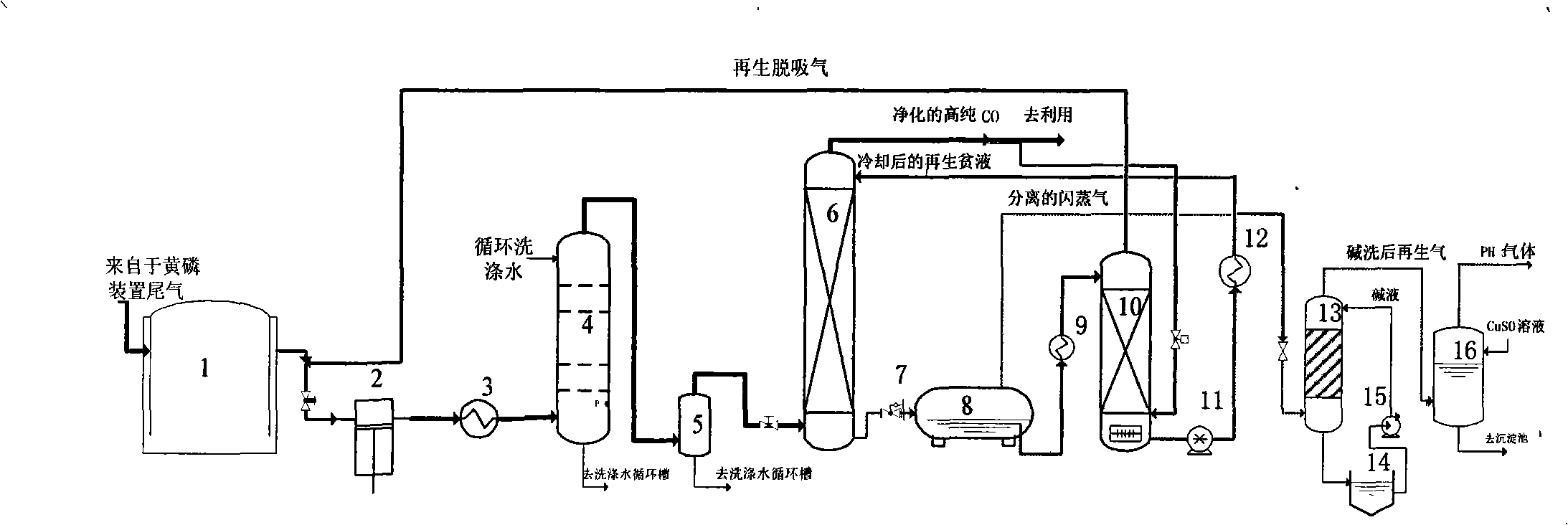
[0035] For the purification process of yellow phosphorus industrial tail gas, please refer to the appendix of the manual figure 1 .

[0036] The normal temperature yellow phosphorus industrial tail gas is sent from the gas storage tank 1 to t...

example 2

[0043] Example 2. The top temperature of a closed calcium carbide furnace in a calcium carbide production enterprise is 400-1000°C. The production of calcium carbide per ton needs to produce 400Nm 3 Furnace gas. The composition of the tail gas of the calcium carbide furnace after dedusting and cooling is shown in the table below.

[0044] Data sheet of each component of calcium carbide furnace tail gas

[0045]

Component

CO

%(V)

CO 2

%(V)

o 2

%(V)

N 2

%(V)

CH 4

%(V)

h 2

%(V)

h 2 S

g / Nm 3

HCN

g / Nm 3

content

75~90

2.6~5.1

0.2~05

1.0~2.0

2.0~4.0

7.0~15.0

5.53~11.56

0.34~1.45

[0046] Note: Other components are saturated water vapor and other inert gases.

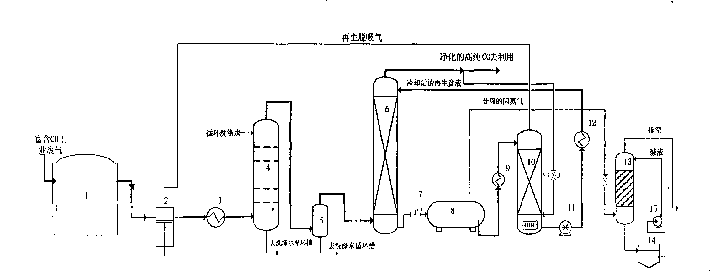
[0047] For the process flow of calcium carbide furnace tail gas purification, please refer to the appendix of the manual figure 2 .

[0048]...


PUM

PropertyMeasurementUnit
Heightaaaaaaaaaa

Abstract

The invention relates to a method taking composite solvents, such as dimethyl ether of polyethlene glycol and the like, as an absorbent to purify industrial tail gas rich in CO, which belongs to the technical field of the clean production of chemical industry. In the method, the counterflow physical absorption of the impurity components of H2S, PH3, HCN, HF, AsH3 and the like in the tail gas is carried out in an absorption tower by utilizing the composite solvents of the method under the conditions of low temperature or normal temperature and 0.1 to 3.5 MPa (gage pressure) after the industrial tail gas rich in the CO is washed by water and dewatered, and the removal rate of the main impurity components reaches more than 99 percent. Absorption liquid which flows out from the bottom of the absorption tower and is rich in the impurity components is throttled, decompressed and heated by a flash evaporator to escape most of the impurity components, the absorption liquid enters a regenerating tower after being reheated and is in counterflow contact with part of refluent purified gas, and impurities are further desorbed. The absorption liquid after being desorbed by the regenerating tower is delivered to the absorption tower for recycle, and the desorption gas of the regenerating tower is delivered back to an inlet of a purification system. The high-concentration foreign gas escaping from the flash evaporator is utilized after alkali washing or copper sulfate liquid washing.

Description

technical field [0001] The invention relates to a method for purifying industrial tail gas containing high-concentration CO by using a composite solvent such as polyethylene glycol dimethyl ether as the main component, and relates to the absorption in the purification process and the analytical regeneration process of the absorbent. The invention belongs to the technical field of chemical clean production. Background technique [0002] In my country's energy structure, coal is the mainstay. With the development of coal chemical technology at home and abroad in recent years, the use and demand of coal and coke in heavy industries such as chemical industry and metallurgy have increased year by year. Coal and ore as raw materials or fuels contain a certain amount of toxic and harmful impurities, and many chemical, calcium carbide and metallurgical production enterprises use coal or coke as a reducing agent, and a large amount of CO (about 90% About) industrial tail gas, theref...

Claims


Application Information

Patent Timeline
IPC IPC(8): B01D53/78
Inventor 毕亚凡冉迎玖
Owner 毕亚凡
Learn More