
High-power semiconductor laser optical output module capable of being reused

An output module and laser technology, applied in the field of lasers, can solve the problems of asymmetry of semiconductor laser bar light spots, increase of system cost and difficulty of debugging, high cost of beam conversion system, etc., to achieve small size, power increase, volume reduction and effect of weight

Inactive Publication Date: 2010-10-13
CHANGCHUN INST OF OPTICS FINE MECHANICS & PHYSICS CHINESE ACAD OF SCI
View PDF8 Cites 17 Cited by
  • Summary
  • Abstract
  • Description
  • Claims
  • Application Information

AI Technical Summary

Problems solved by technology

[0003] At present, the semiconductor laser module that achieves high power output with a single optical fiber mainly has the following problems: 1) The bar light spot of the semiconductor laser used as the coupling unit is asymmetrical and cannot directly enter the optical fiber. The beam conversion system is expensive and complicated to install and adjust, which undoubtedly increases the cost of the system and the difficulty of debugging; 2) The laser with a power exceeding 60W needs to be cooled by a water-cooling system, which increases the volume and weight of the entire system and is not suitable for practical applications. Convenient; 3) Although semiconductor lasers have a long life, it is inevitable that there will be poor-quality lasers. The general system is not easy to replace the laser. Once a low-quality laser appears in the system, this will lead to a decline in the performance of the entire system
At present, only 2 of the US patent "semiconductor diode lasers with a specific geometry, US6124973, Frannhofer, 2000; Modular diode laser assembly, US0268946, nlight, 2007; Diode laser arrangement with a plurality of diode laser arrays, US689822, Jenoptik Laserdiode" A base, only one row of lasers on the base, low power

Method used


Image

  • High-power semiconductor laser optical output module capable of being reused
  • High-power semiconductor laser optical output module capable of being reused
  • High-power semiconductor laser optical output module capable of being reused

Examples


Embodiment Construction

[0016] The specific implementation manners of the present invention will be described in detail below in conjunction with the accompanying drawings.

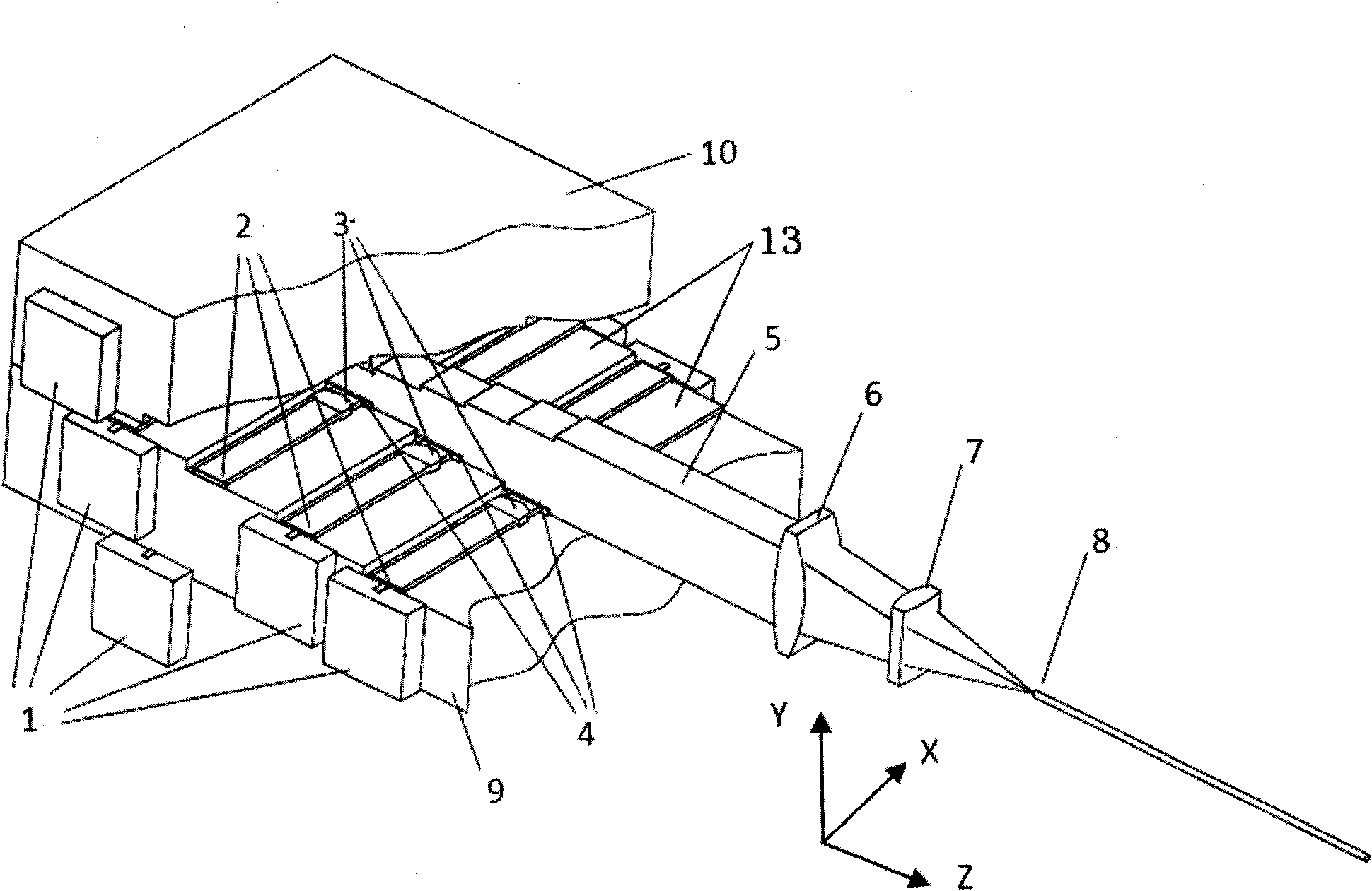
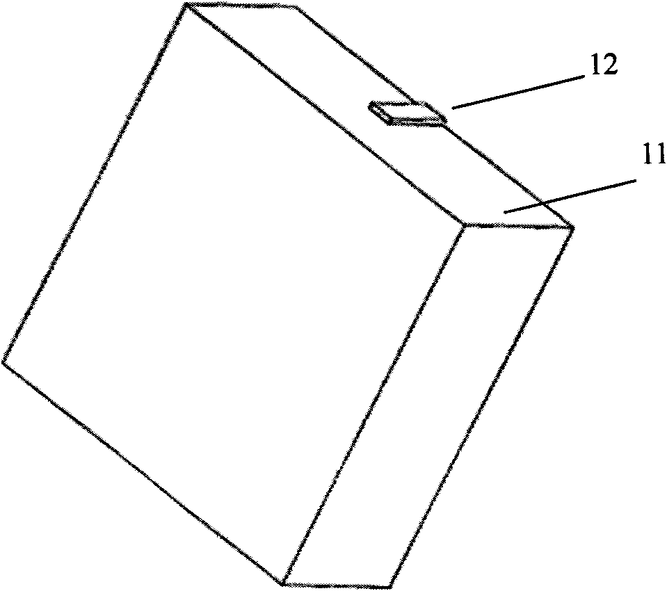
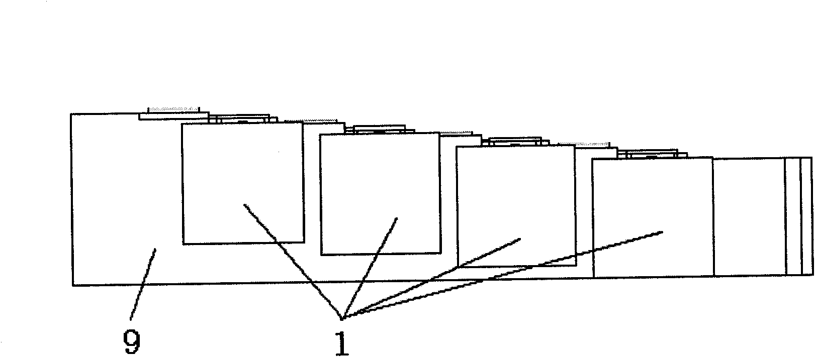
[0017] Depend on Figure 1-7 As shown, the present invention includes a laser beam shaping system, a focusing system, an upper stepped base 10, and a lower stepped base 9. The upper stepped base 10 and the lower stepped base 9 are fastened through each other's upper end surfaces, and the laser beam shaping system is installed on the upper, lower stepped base 9. On the steps 13 of the lower stepped base, the focusing system is located in the direction of the outgoing light outside the upper and lower stepped bases. The steps 13 on the said lower stepped base 9 are staggered, and the steps 13 on different sides are in the middle of the lower stepped base 9. The contact surface is V-shaped, and the contact surface of the whole step 13 is V-shaped wave. The said upper stepped base 10 has the same structure as the lower stepped base ...


PUM


Abstract

The invention relates to the laser field, in particular to a high-power semiconductor laser optical output module capable of being reused. The invention comprises a laser beam reshaping system, a focusing system, an upper ladder base and a lower ladder base. The upper ladder base and the lower ladder base are buttoned together through a respective upper end plane. The laser beam reshaping system is arranged on the steps of the upper ladder base and the lower ladder base. The focusing system is located in the emergent light direction outside the upper ladder base and the lower ladder base. The steps on the lower ladder base are staggered. The contact faces of the steps at different sides in the middle of the lower ladder base present a V shape. The whole step contact face presents V-shaped waves. The structures of the upper ladder base and the lower ladder base are the same. The invention can be reused, has no water cooling and small size and can realize high-power high-light output.

Description

technical field [0001] The invention relates to the field of lasers, in particular to a reusable high-power semiconductor laser fiber output module. Background technique [0002] Semiconductor lasers are used in various aspects of industry and military due to their small size, light weight and high conversion efficiency. However, due to the inherent defects of semiconductor lasers, the beam quality in the slow axis direction is far worse than that in the fast axis direction, the output spot is asymmetrical, and the energy distribution is uneven, which limits its application in some occasions that require high beam quality. The light output through the optical fiber has the advantages of rounded spot and uniform energy distribution. At the same time, it can also achieve arbitrary angle and long-distance transmission. Therefore, the light output through the optical fiber can be well used in laser cutting and laser in industrial processing. punching etc. At the same time, as ...

Claims


Application Information

Patent Timeline
Patent Type & Authority Applications(China)
IPC IPC(8): G02B27/09H01S5/40
Inventor 张俊王立军王琪郝明明张志军
Owner CHANGCHUN INST OF OPTICS FINE MECHANICS & PHYSICS CHINESE ACAD OF SCI
Learn More