Line loss compensation circuit for switch power supply

A line loss compensation, switching power supply technology, applied in electrical components, output power conversion devices, AC power input into DC power output and other directions, can solve the problem of losing the constant control of the output terminal.

Inactive Publication Date: 2010-10-13
西安英洛华微电子有限公司
View PDF0 Cites 47 Cited by
  • Summary
  • Abstract
  • Description
  • Claims
  • Application Information

AI Technical Summary

Problems solved by technology

[0003] The problem with the above-mentioned switching power supply system is that in general, the voltage regulation is adjusted for a variable of the load (Load).
[0015] From the above formulas (1'), (2'), and (3'), it can be seen that when the output wire is selected, its loss resistance Rcable is a certain value, but the output current Iout is a variable that changes with the load Load , therefore, there are two variables Vout and Iout in formulas (1'), (2'), and (3'), but the control loop only regulates the voltage of Vout, and does not regulate the voltage of Iout, so , the control loop loses constant control of the output

Method used


Image

  • Line loss compensation circuit for switch power supply
  • Line loss compensation circuit for switch power supply
  • Line loss compensation circuit for switch power supply

Examples


Embodiment 1

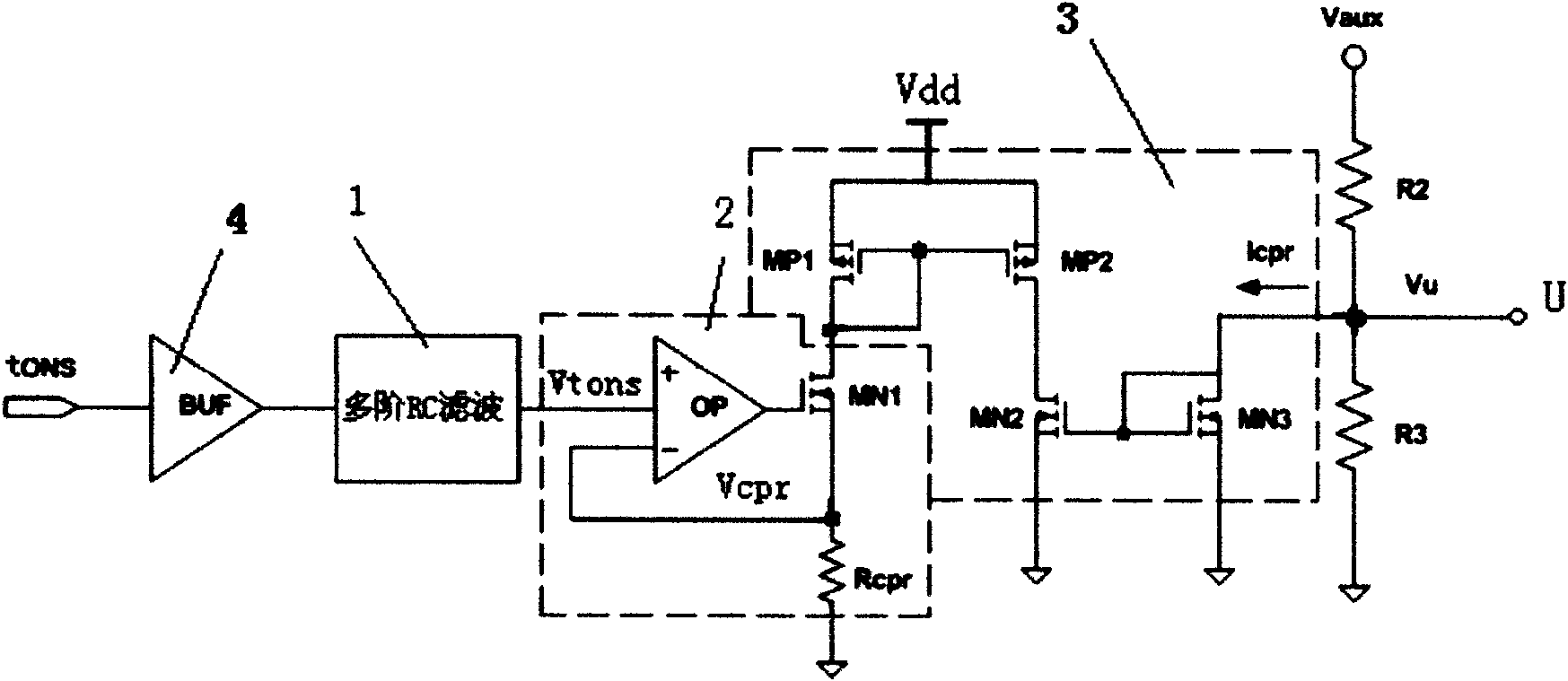
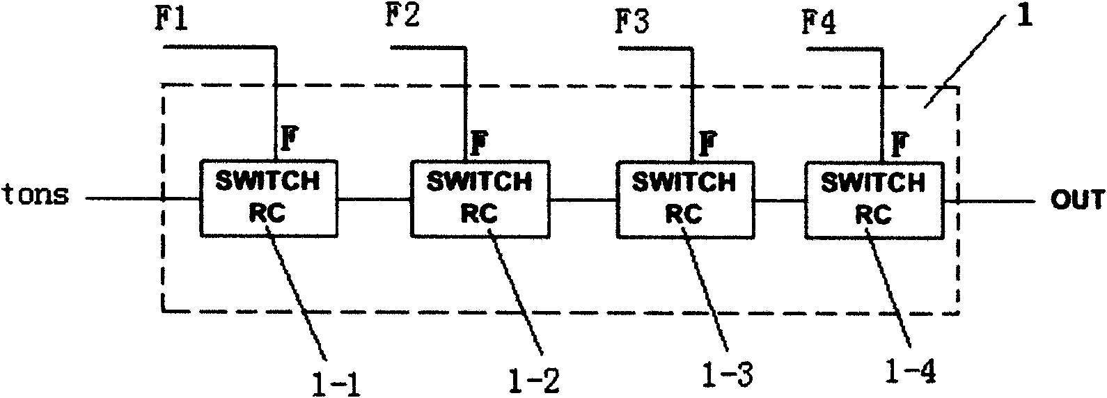
[0030] see figure 1 , 5 , the line loss compensation circuit of this example is composed of a fourth-order RC low-pass filter 1, a voltage / current conversion circuit 2 and a current mirror circuit 3, the input of the fourth-order RC low-pass filter 1 is directly or through A buffer 4 is connected to the line loss detection signal terminal tons, and the voltage / current conversion circuit 2 is composed of an operational amplifier OP, a power switch MN1 and a compensation resistor Rcpr connected in series to the drain of the power switch MN1 , the positive input terminal of the operational amplifier OP is connected to the output terminal of the fourth-order RC filter 1, the negative input terminal of the operational amplifier is connected to the drain of the power switch tube MN1, and the output of the operational amplifier 2 The terminal is connected to the gate of the power switch tube MN1. The current mirror circuit 3 is formed by connecting two common grid mirror circuits,...

Embodiment 2

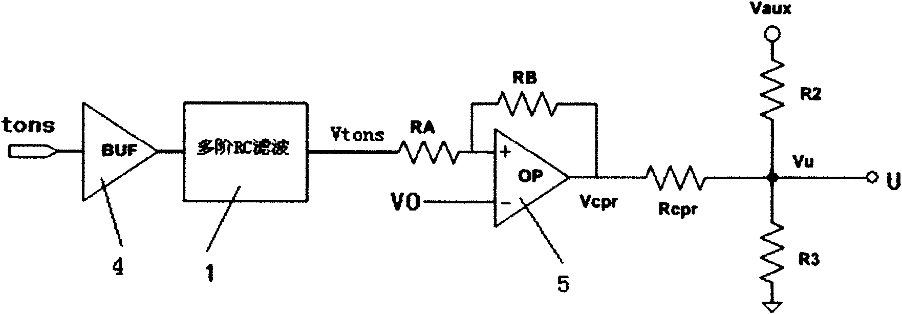
[0058] see Figure 4 , 5 , it consists of a fourth-order RC low-pass filter 1, a subtractor 5 and a compensation resistor Rcpr, the output of the RC low-pass filter is connected to the positive input of the subtractor, and the negative input of the subtractor is connected to the reference The voltage V0 is connected, and the output terminal of the subtractor is connected to the Figure 5 On the sampling voltage input terminal U of the switching power supply.

[0059] Same as Embodiment 1, when the input tons signal becomes a DC voltage signal Vtons=Vdd*Tons*f that changes with the tons signal after the fourth-order low-pass filter, after the signal passes through the subtractor, the output compensation voltage Vcpr:

[0060] Vcpr=V0-Vtons

[0061] In the formula, V0 is the reference voltage, and the compensation voltage Vcpr is added to the U terminal through the compensation resistor Rcpr. from figure 2 It can be seen that the current flowing through R2 from the sampling...


PUM


Abstract

The invention relates to a line loss compensation circuit for a switch power supply, which is divided into a current-type line loss compensation circuit and a voltage-type line loss compensation circuit, wherein the current-type circuit comprises a multi-stage RC low pass filter, a voltage / current switching circuit and a current mirroring circuit, and the voltage-type circuit comprises a multi-stage RC low pass filter, a subtractor and a compensating resistance. The invention can produce a compensating current of Icpr or a compensating voltage of Vcpr which is proportionable to an output current of Iout, and the compensating current or the compensating voltage is used for offsetting voltage drop of an output wire caused by change of Iout, thereby recovering voltage stabilizing control function of a control loop to secure constant output. The invention has the advantages of skilful design idea and simple circuit and is easy to realize. The improvement of the invention is that: the switch RC filter is adopted to greatly reduce volume of an electric capacity of the RC filter, thereby facilitating integration, further improving circuit performance and simplifying circuit structure, and strengthening operation reliability of the switch power supply.

Description

technical field [0001] The invention relates to a line loss compensation circuit of an AC-DC switching power supply. Background technique [0002] In the existing technology, AC-DC switching power supply generally adopts a flyback primary side control method, such as Figure 5 As shown, with this architecture, the system does not need to use the optocoupler to feedback sampling at the secondary output of the output transformer, but uses the sampling of the primary auxiliary terminal (Vaux) of the output transformer to perform loop control. Its working process is: the input AC alternating current is converted into a DC signal Vin after full-wave rectification by diodes D1~D4 and filtering by capacitor C1. On the one hand, the DC signal Vin charges the capacitor C2 through the starting resistor R1. When the capacitor C2 is on After the voltage reaches the start-up voltage Vp of the voltage regulator control chip X3, the chip X3 starts to work; on the other hand, the DC signal ...

Claims


Application Information

Patent Timeline
Patent Type & Authority Applications(China)
IPC IPC(8): H02M7/217
Inventor 宋利军郭晋亮卢璐方建平
Owner 西安英洛华微电子有限公司
Why Eureka
Try Eureka