Line loss compensation circuit for switch power supply
A line loss compensation and circuit technology, applied in electrical components, output power conversion devices, conversion of AC power input to DC power output, etc., can solve the problem of losing the constant control of the output terminal.
- Summary
- Abstract
- Description
- Claims
- Application Information
AI Technical Summary
Problems solved by technology
Method used
Image
Examples
Embodiment 1
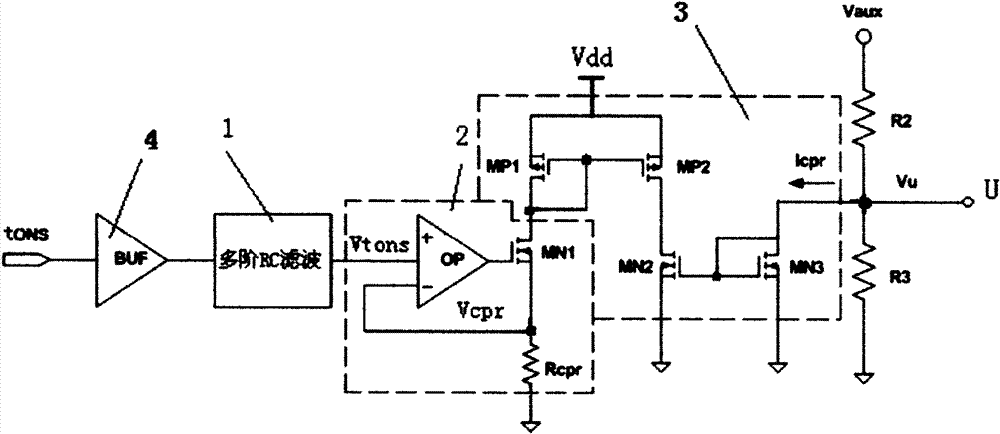
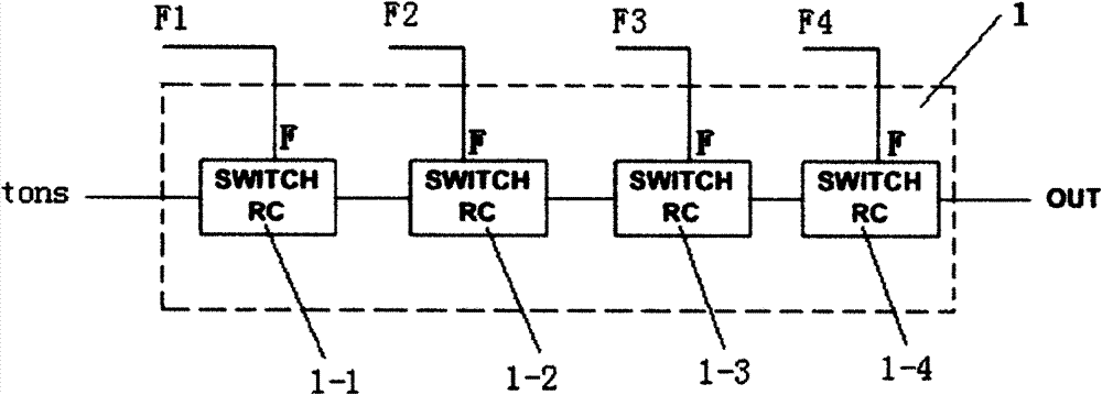
[0030] see figure 1 , 5 , the line loss compensation circuit of this example is composed of a fourth-order RC low-pass filter 1, a voltage / current conversion circuit 2 and a current mirror circuit 3, the input of the fourth-order RC low-pass filter 1 is directly or through A buffer 4 is connected to the line loss detection signal terminal tons, and the voltage / current conversion circuit 2 is composed of an operational amplifier OP, a power switch MN1 and a compensation resistor Rcpr connected in series to the drain of the power switch MN1 , the positive input terminal of the operational amplifier OP is connected to the output terminal of the fourth-order RC filter 1, the negative input terminal of the operational amplifier is connected to the drain of the power switch tube MN1, and the output of the operational amplifier 2 The terminal is connected to the gate of the power switch tube MN1. The current mirror circuit 3 is formed by connecting two common grid mirror circuits,...
Embodiment 2
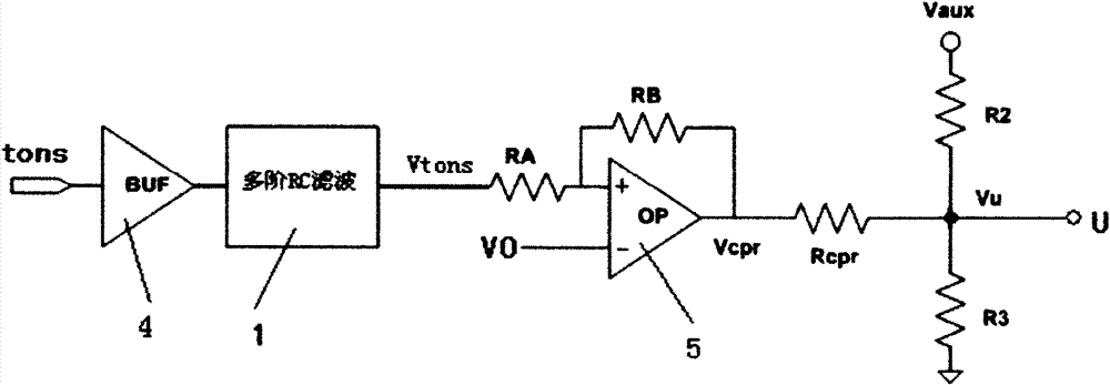
[0058] see figure 2 , 5 , it consists of a fourth-order RC low-pass filter 1, a subtractor 5 and a compensation resistor Rcpr, the output of the RC low-pass filter is connected to the positive input of the subtractor, and the negative input of the subtractor is connected to the reference The voltage V0 is connected, and the output terminal of the subtractor is connected to the Figure 5 On the sampling voltage input terminal U of the switching power supply.
[0059] Same as Embodiment 1, when the input tons signal becomes a DC voltage signal Vtons=Vdd*Tons*f that changes with the tons signal after the fourth-order low-pass filter, after the signal passes through the subtractor, the output compensation voltage Vcpr:
[0060] Vcpr=V0-Vtons
[0061] In the formula, V0 is the reference voltage, and the compensation voltage Vcpr is added to the U terminal through the compensation resistor Rcpr. from figure 2 It can be seen that the current flowing through R2 from the sampling...
PUM
 Abstract
Description
Claims
Application Information
 - R&D
- Intellectual Property
- Life Sciences
- Materials
- Tech Scout
- Unparalleled Data Quality
- Higher Quality Content
- 60% Fewer Hallucinations
Browse by: Latest US Patents, China's latest patents, Technical Efficacy Thesaurus, Application Domain, Technology Topic, Popular Technical Reports.
© 2025 PatSnap. All rights reserved.Legal|Privacy policy|Modern Slavery Act Transparency Statement|Sitemap|About US| Contact US: help@patsnap.com


