Hot wire consumable electrode gas protection welding method and realization device thereof

A melting gas and shielded welding technology, applied in welding equipment, arc welding equipment, manufacturing tools, etc., can solve the problems of poor welding quality, inability to realize heat input of welding wire and molten pool, low welding efficiency, etc., and achieve improved welding efficiency. The effect of improving the quality, improving the quality of the weld seam, and improving the welding efficiency

Inactive Publication Date: 2010-10-20
HARBIN INST OF TECH
View PDF5 Cites 38 Cited by
  • Summary
  • Abstract
  • Description
  • Claims
  • Application Information

AI Technical Summary

Problems solved by technology

[0004] The purpose of the present invention is to solve the problems of low welding efficiency and low welding quality due to the inability to reasonably distribute the heat input of the welding wire and the mol

Method used


Image

  • Hot wire consumable electrode gas protection welding method and realization device thereof
  • Hot wire consumable electrode gas protection welding method and realization device thereof
  • Hot wire consumable electrode gas protection welding method and realization device thereof

Examples


specific Embodiment approach 1

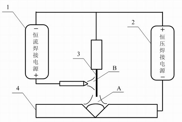
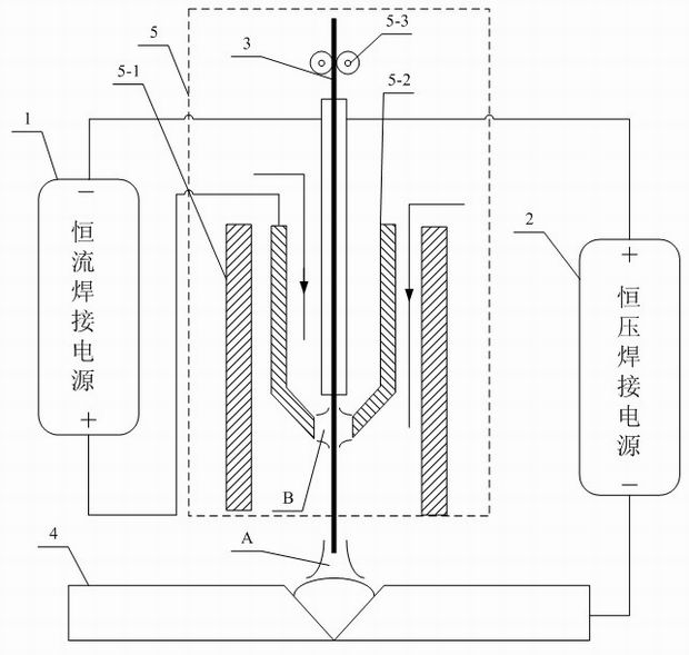
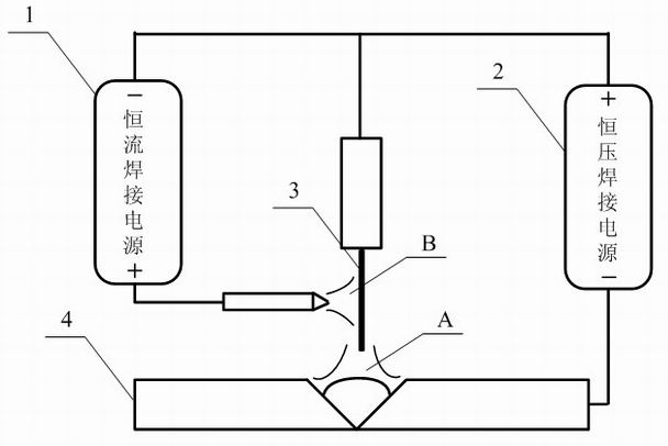
[0012] Specific implementation mode one: the following combination figure 1 and figure 2 Describe this embodiment, this embodiment adopts constant-current welding power source 1 and constant-voltage welding power source 2 to implement, and the positive output end of constant-current welding power source 1 is connected with the conductive ring sleeve 5-2 of welding torch 5, and constant-current welding power source 1 The negative output terminal of the welding torch 5 is connected to the electrode clamp 5-3 of the welding torch 5, and the melting electrode welding wire 3 is clamped on the electrode clamp 5-3 of the welding torch 5; the positive output terminal of the constant voltage welding power supply 2 is connected to the electrode clamp 5-3 of the welding torch 5 connection, the negative output end of the constant voltage welding power supply 2 is connected to the workpiece 4 to be welded, and its welding method is:

[0013] Put the end of the consumable electrode wire 3...

specific Embodiment approach 2

[0022] Specific Embodiment 2: This embodiment is a further limitation of Embodiment 1. In this embodiment, the main arc adopts CO 2 Gas or other mixed gas for protection. Others are the same as the first embodiment.

specific Embodiment approach 3

[0023] Embodiment 3: This embodiment is a further limitation of Embodiment 1. In this embodiment, the preheating arc is protected by Ar gas. Others are the same as the first embodiment.

[0024] The shielding gas Ar is passed between the conductive annular sleeve 5-2 of the welding torch 5 and the electrode holder 5-3 to protect the preheating arc, which can prevent the preheating arc and the consumable electrode wire 3 from being attacked by gases such as oxygen, nitrogen, and hydrogen. Adjust the parameters of the constant current welding power source 1 to ensure that the preheating arc burns stably under the protection of the Ar inert atmosphere. The melting electrode welding wire 3 is continuously fed through the wire feeding device. The welding main arc is generated in between. The heat of the main arc continuously melts the melting electrode welding wire 3 to form molten droplets, which stably transition to the molten pool, and the wire feeder continuously feeds the mel...


PUM


Abstract

The invention relates to a hot wire consumable electrode gas protection welding method and a realization device thereof, which belong to the technical field of welding. The invention solves the problems of low welding efficiency and low welding quality in the existing consumable electrode gas protection welding method and the device for realizing the welding method caused by incapability of realizing the reasonable distribution of welding wires and hot input of fusing tanks. The welding method comprises the following steps: placing the tail end of the consumable electrode welding wire near a part to be welded of a work piece to be welded; forming a main arc between the tail end of the consumable electrode welding wire and the surface to be welded of the work piece to be welded under the effect of a constant voltage welding power supply for realizing the welding; placing the tail end of a conductive annular sleeve of a welding gun near the side wall of the consumable electrode welding wire in the welding process; and forming a preheating electric arc between the tail end of the conductive annular sleeve of the welding gun and the side wall of the consumable electrode welding wire under the effect of a constant current welding power supply for realizing the preheating on the consumable electrode welding wire. The realization device consists of the constant current power supply, the constant voltage welding power supply and the welding gun. The invention is used for the implementation of the gas protection welding.

Description

technical field [0001] The invention relates to a hot wire melting electrode gas shielded welding method and a device for realizing it, and belongs to the field of welding technology. Background technique [0002] With the rapid development of the manufacturing industry and the continuous improvement of welding technology, welded structures have been widely used. Due to the huge amount of welding work, the work efficiency of traditional welding methods can no longer meet the needs of welding tasks, so various efficient welding methods have become a research hotspot. Among many welding methods, MIG welding is widely used in high-efficiency welding methods because of its advantages such as easy automation, all-position welding, energy saving and good joint quality. In the existing welding methods of MIG arc welding, the high-efficiency means adopted include: using multi-component mixed gas protection, increasing the welding current and using composite heat sources, etc. The c...

Claims


Application Information

Patent Timeline
IPC IPC(8): B23K9/173B23K9/10B23K9/235
Inventor 高洪明倪俊李海超张广军
Owner HARBIN INST OF TECH
Why Eureka
Try Eureka