Power amplifier circuit with reconfigurable frequency band in multi-band wireless mobile communication system

A technology for mobile communication systems and power amplifiers, which is applied in power amplifiers, high-frequency amplifiers, transmission systems, etc., and can solve problems that affect the application and further development of multi-band wireless mobile communication systems, difficulty in fully integrating chips, and large chip areas. , to achieve the effect of simple structure, perfect function and simple chip structure

Active Publication Date: 2010-10-20
INST OF ELECTRONICS CHINESE ACAD OF SCI
View PDF0 Cites 31 Cited by
  • Summary
  • Abstract
  • Description
  • Claims
  • Application Information

AI Technical Summary

Problems solved by technology

This structure has the disadvantages of large chip area, high power consumption, and difficulty in realizing full chip integration, which seriously affects the application and further development of multi-band wireless mobile communication systems.

Method used


Image

  • Power amplifier circuit with reconfigurable frequency band in multi-band wireless mobile communication system
  • Power amplifier circuit with reconfigurable frequency band in multi-band wireless mobile communication system
  • Power amplifier circuit with reconfigurable frequency band in multi-band wireless mobile communication system

Examples


Embodiment 1

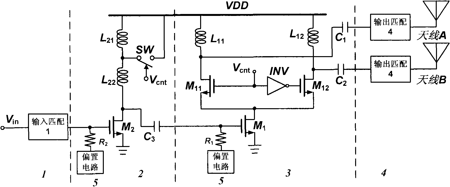
[0032] The input matching unit 1 embodiment of the present invention is such as figure 2 As shown in , the impedance matching between the RF signal source and the input stage unit 2 can be realized in the frequency band range from hundreds of MHz to several GHz (such as 200MHz bandwidth, 1GHz bandwidth, 3GHz bandwidth, 7GHz bandwidth, etc., not to be described in detail). , and provides flat gain;

[0033] The input stage unit 2 embodiment structure of the present invention is as follows figure 2 As shown in, by the transistor M2, the first inductor L 21 , the second inductance L 22 , controllable switch SW, capacitor C 3 , bias unit 5, resistor R 2 A common source amplifier circuit is formed to pre-amplify the matched input radio frequency signal. By controlling the on-off state of the controllable switch SW, the value of the inductance connected to the drain terminal of the input stage unit 2 (L 22 or L 21 +L 22 ), changing the drain inductance and capacitance C 3...

Embodiment 2

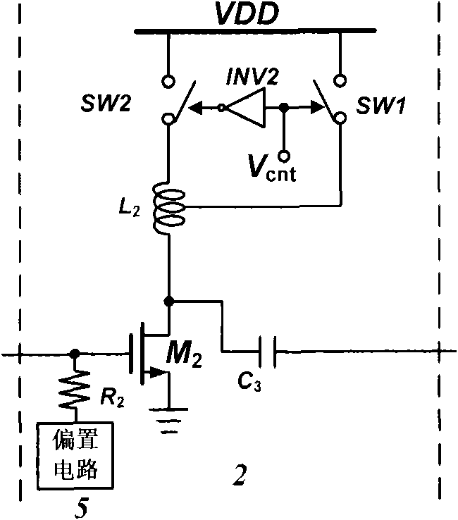
[0040] The structure of the power amplifier circuit adopted in this embodiment, in which the input matching unit 1 , the output stage unit 3 , the output matching unit 4 and the bias unit 5 are all the same as those in the embodiment 1, will not be repeated here. The only difference between this embodiment and Embodiment 1 is that the selection of the drain inductance of the input stage transistor M2 is not determined by figure 2 The first inductance L shown 21 , the second inductance L 22 And the combination of controllable switch SW to complete, but by a switch inductor, two controllable switches and an inverter to complete, as attached image 3 shown.

[0041] In this embodiment, the input stage unit 2 contains a switching inductance L 2 , controllable switch SW1, SW2, inverter INV2, resistor R 2 , transistor M2, interstage capacitor C 3 , switching inductance L 2 One end of the transistor M2 is connected to the drain terminal, one end is connected to the controllabl...


PUM


Abstract

The invention relates to a power amplifier circuit with a reconfigurable frequency band in a multi-band wireless mobile communication system, belonging to a radiofrequency integrated circuit technology and the processing field of analog signals. The power amplifier circuit comprises an input stage unit, an output stage unit, an input matching unit, an output matching unit and a bias unit, whereinthe input stage unit is respectively connected with a radiofrequency signal source and a grid of the input stage unit, the input stage unit is respectively connected with the input matching unit and the output stage unit, the output stage unit is respectively connected with the circuits of the input stage unit and the output matching unit corresponding to different resonant frequencies, the output matching unit is respectively connected with the output stage unit and a corresponding transmitting antenna, and the bias unit respectively provides bias voltage to the amplifier tubes of the input stage unit and the output stage unit. The invention can fulfill a function of power amplification of radiofrequency signals at different frequency bands in the multi-band wireless mobile communicationsystem and has the advantages of simple structure, perfect function and the like.

Description

technical field [0001] The invention belongs to the field of radio frequency integrated circuit technology and analog signal processing in a multi-band wireless mobile communication system, and particularly relates to multi-band wireless devices such as wireless local area network (WLAN), wireless metropolitan area network (WiMAX), and advanced international mobile communication technology (IMT-advanced). The structural design of the reconfigurable power amplifier circuit in the middle frequency band of the wireless transceiver of the mobile communication system. Background technique [0002] With the development of wireless mobile communication technology, the wireless mobile communication system is developing from 2G and 3G to 3G+ and 4G, and multi-band communication standards have emerged. For example, WLAN works in two frequency bands of 2.4GHz and 5.2GHz, and WiMAX can work in two frequency bands of 3.5GHz and 2.5GHz; the International Telecommunication Union named the ...

Claims


Application Information

Patent Timeline
Patent Type & Authority Applications(China)
IPC IPC(8): H03F3/20H03F3/189H04B1/00
Inventor 高同强杨海钢
Owner INST OF ELECTRONICS CHINESE ACAD OF SCI
Why Eureka
Try Eureka