Solar energy and methanol fuel chemical-looping combustion power generation system and method

A chemical chain combustion, methanol fuel technology, applied in the directions of light radiation generators, generators/motors, machines/engines, etc., can solve the problem of low initial temperature at the inlet of gas turbines, and achieve high initial temperature, simple structure, and reduced Effect of use of fuel

Active Publication Date: 2010-11-17
INST OF ENGINEERING THERMOPHYSICS - CHINESE ACAD OF SCI
View PDF0 Cites 22 Cited by
  • Summary
  • Abstract
  • Description
  • Claims
  • Application Information

AI Technical Summary

Problems solved by technology

[0011] In view of this, the object of the invention is to propose a control CO 2 The chemical looping combustion power generation system and method in which discharged solar energy and methanol fuel are complementary solves the problem of low initial temperature at the gas turbine inlet caused by the limitation of circulating materials in the chemical looping combustion power system. CO 2 capture energy consumption

Method used


Image

  • Solar energy and methanol fuel chemical-looping combustion power generation system and method
  • Solar energy and methanol fuel chemical-looping combustion power generation system and method
  • Solar energy and methanol fuel chemical-looping combustion power generation system and method

Examples


Embodiment 1

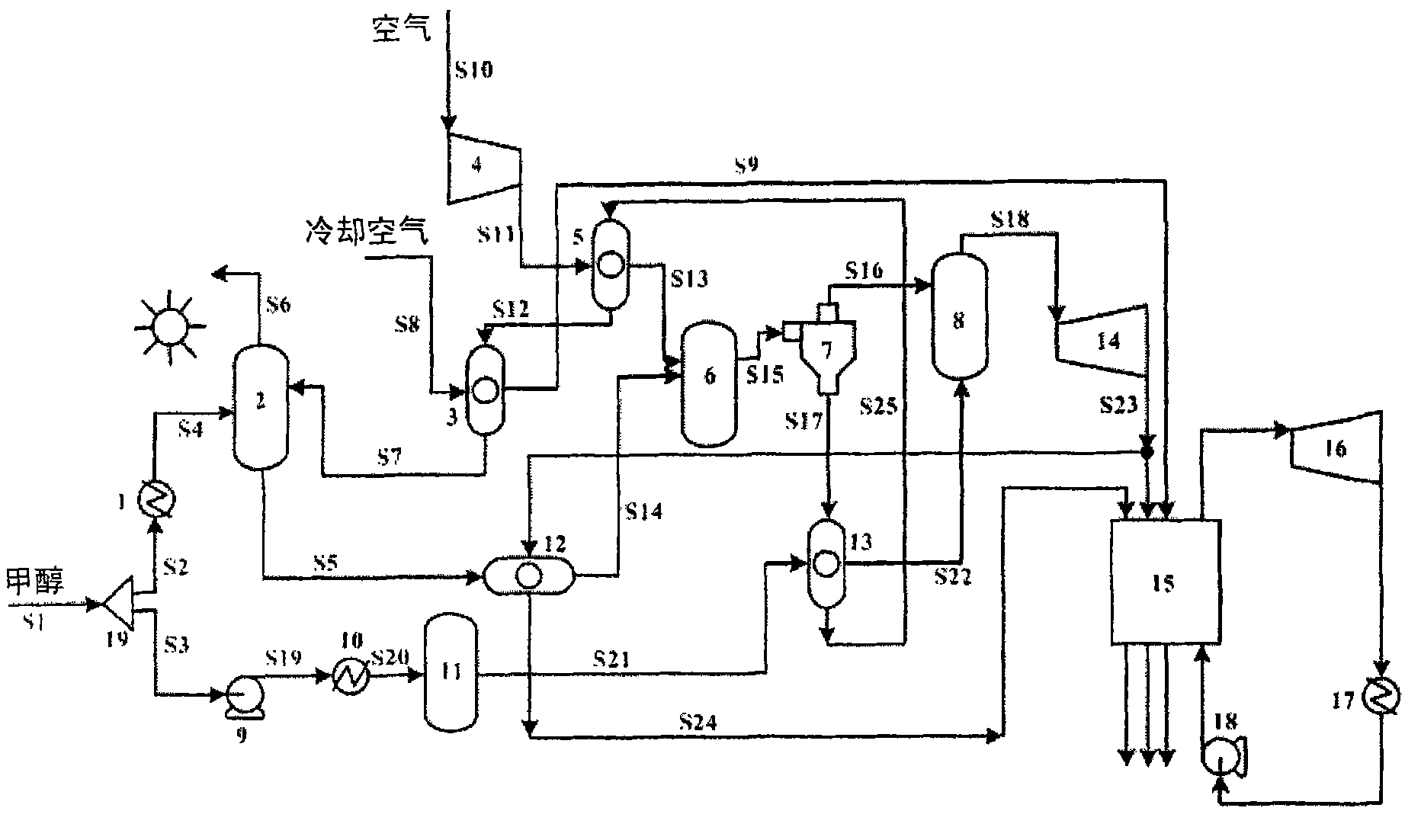
[0047] The present embodiment system consists of preheaters 1, 10, pumps 9, 18, gas-solid heat exchangers 3, 5, 12, 13, flow splitter 19, solar heat collection-reduction reactor 2, solar heat collection-decomposition reactor 11. Oxidation reactor 6, compressor 4, cyclone separator 7, afterburning combustion chamber 8, gas turbine 14, waste heat boiler 15, steam turbine 16, and condenser 17. The specific process is:

[0048] Methanol S1 is divided into two streams S2 and S3 through the flow divider 19 and enters the system. Methanol S2 enters the solar energy collection-reduction reactor 2 after being preheated by the preheater 1, and the preheating heat source is gathered by the trough solar collector 200 ~ 300 ℃ medium and low temperature solar thermal energy. In the reduction reactor, methanol and Fe 2 o 3 The circulating particles S7 undergo a reduction reaction. After the reaction, methanol is oxidized to the gaseous product CO 2 and water vapor S6, Fe 2 o 3 It is r...

Embodiment 2

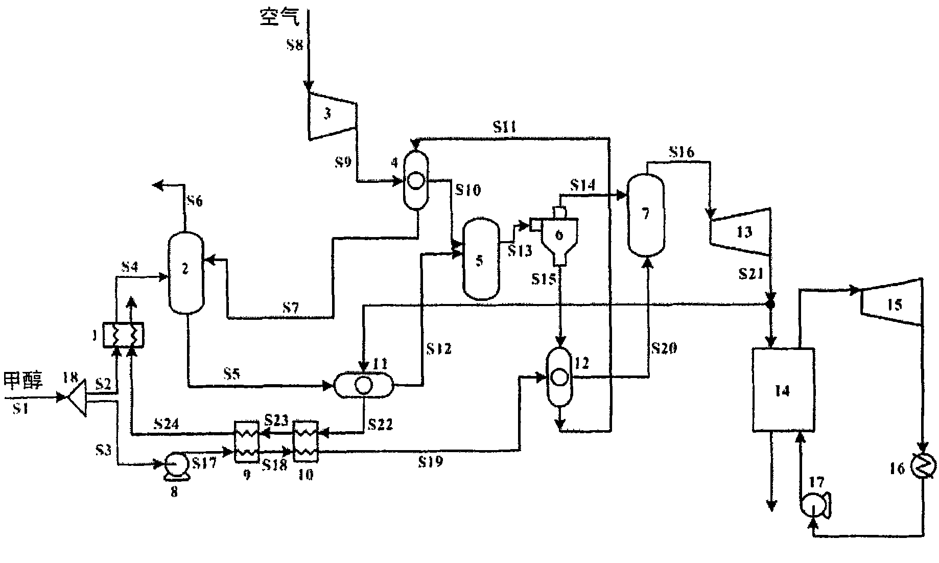
[0051] The present embodiment system consists of preheaters 1, 9, pumps 8, 17, gas-solid heat exchangers 4, 11, 12, splitter 18, reduction reactor 2, decomposition reactor 10, oxidation reactor 5, compressor 3 , cyclone separator 6, afterburning combustion chamber 7, gas turbine 13, waste heat boiler 14, steam turbine 15, and condenser 16. The specific process is:

[0052] Methanol S1 is divided into two streams S2 and S3 through the flow divider 18 and enters the system. Methanol S2 enters the reduction reactor 2 after being preheated by the preheater 1, and the preheating heat source is waste heat of flue gas. In the reduction reactor, methanol and Fe 2 o 3 The circulating particles S7 undergo a reduction reaction. After the reaction, methanol is oxidized to the gaseous product CO 2 and water vapor S6, Fe 2 o 3 is reduced to FeO solid particles S5, the reaction heat required by the circulating particles Fe 2 o 3 The sensible heat carried by itself is provided. The r...


PUM


Abstract

The invention relates to the technical fields of the solar thermal power generation and energy, in particular to a solar energy and methanol fuel chemical-looping combustion power generation system and method used for controlling CO2 emission. The intermediate-low temperature solar thermochemical process and the chemical-looping combustion power cycle are coupled organically to form the system ofthe invention. The system comprises a solar heat collecting-reduction reactor, a solar heat collecting-decomposition reactor, an oxidation reactor, an afterburning combustion chamber, a gas turbine, a steam turbine, an exhaust-heat boiler, a heat exchanger and the like. By using the device of the invention, the graded use of energy resources with different qualities can be realized; the zero-energy separation of CO2 can be realized through simple condensation; the combustion method can reduce the fuel grade to FeO grade, thus reducing the fuel loss in the combustion process and increasing theefficiency of the system; the solar thermochemical reaction is adopted to improve the grade of intermediate-low temperature solar energy; and afterburning is adopted so as to solve the problem that the gas turbine inlet has low initial temperature caused by the limit of the cycle material in the chemical-looping combustion power system.

Description

technical field [0001] The invention relates to the field of solar thermal power generation and energy technology, in particular to a method for controlling CO 2 A chemical looping combustion power generation system and method in which exhausted solar energy and methanol fuel are complementary. Background technique [0002] CO 2 As the main greenhouse gases emitted by humans into the atmosphere, most of them come from the combustion of fossil fuels such as coal, oil, and natural gas, of which 29% come from power generation. Currently, CO 2 The emission reduction can be achieved by adjusting the energy structure and improving energy conversion and utilization efficiency. [0003] From the perspective of adjusting the energy structure, renewable energy, especially solar energy, has high hopes. With the advantages of "infinite" reserves, universality of existence, cleanness of development and utilization, and gradually revealed economical advantages of solar energy, many de...

Claims


Application Information

Patent Timeline
Patent Type & Authority Applications(China)
IPC IPC(8): H02N6/00F01K11/02F01K27/02
Inventor 金红光洪慧隋军刘启斌韩涛
Owner INST OF ENGINEERING THERMOPHYSICS - CHINESE ACAD OF SCI
Why Eureka
Try Eureka