Method and device of fluorescence microscopy by using pyramid lens to generate structured lighting

A structured lighting and quadrangular pyramid technology, applied in microscopes, optics, optical components, etc., can solve the problems of large light field distortion and low light energy utilization, and achieve weak image distortion effects, reduce light damage, and reduce total power. Effect

Active Publication Date: 2010-11-24
BEIJING LUSTER LIGHTTECH
View PDF1 Cites 12 Cited by
  • Summary
  • Abstract
  • Description
  • Claims
  • Application Information

AI Technical Summary

Problems solved by technology

[0006] The present invention proposes a method and device for microstructural illumination by using a four-beam interference field generated by a quadrangular pyramid mirror, which solves the technical problems of large light field distortion and low utilization rate of light energy in existing structured illumination microscopic techniques

Method used


Image

  • Method and device of fluorescence microscopy by using pyramid lens to generate structured lighting
  • Method and device of fluorescence microscopy by using pyramid lens to generate structured lighting
  • Method and device of fluorescence microscopy by using pyramid lens to generate structured lighting

Examples


Embodiment

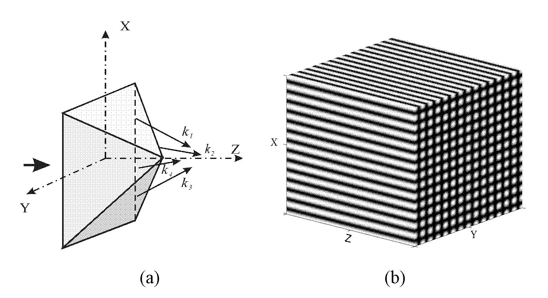
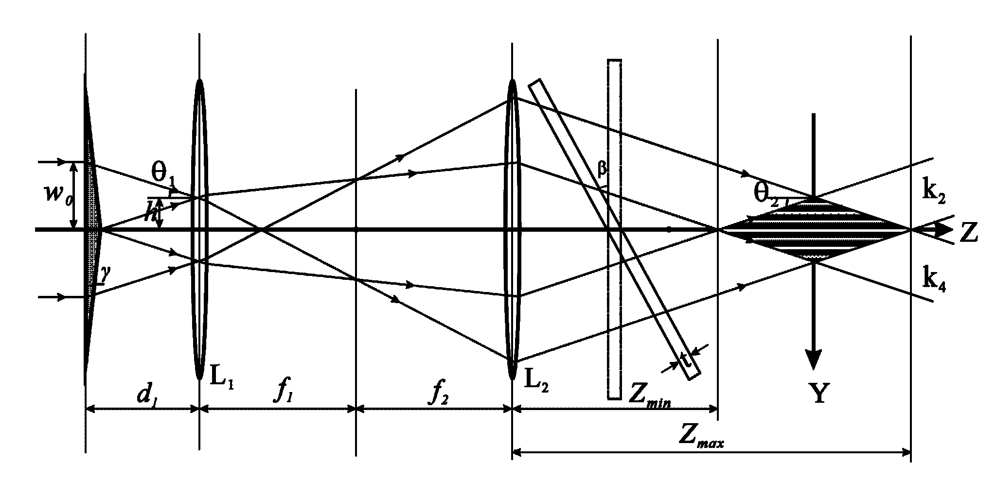
[0054] Example: In the experiment, a quadrangular pyramid mirror with a base angle=7° is used, and the refractive index of the material is n 0 =1.5, laser wavelength =532nm, radius w of the incident laser beam 0 =1.5mm, lens L 1 Focal length f 1 =125mm, lens L 2 Focal length f 2 =50mm, d 1 = 5mm. Substituting into the formula (3-5), the structured illumination light field period Δ=1.75m, Z max =77mm, Z min = 73mm. This greatly increases the working distance of the system and facilitates the placement of components such as the sample stage and the microscope objective lens.

[0055] Such as figure 2 As shown (in the YZ plane), in the lens L 2 Then place a thickness of t and refractive index of n 1 Glass pieces. The glass sheet will not change the angle of the beam, but will give the interference beam k 2 With k 4 There is a phase difference between:

[0056] δ = 2 π λ ( n 1 t cos ( β + θ 2 ) - n 1 t cos ( ...


PUM


Abstract

The invention provides a method and a device of fluorescence microscopy by using a pyramid lens to generate structured lighting. The device comprises parallel beams, a structured lighting system, a sample cell and an image acquisition system, wherein the structured lighting system comprises a pyramid lens, a telescope system and a phase-shifting glass sheet; and the sample cell is arranged at the rear part of the phase-shifting glass sheet. The parallel beams are refracted after passing through the pyramid lens, thus generating a four-beam interference field with two-dimensional space structure distribution and exciting a sample by the four-beam interference field. The three-dimensional tomography can be realized through image processing algorithm by translating the interference optical field acted on the sample Compared with the existing microscopy for structured lighting, the invention can achieve higher axial resolution but lower photo-bleaching effect. Therefore, the invention is suitable for the research on the imaging of living creatures.

Description

Technical field [0001] The invention relates to a fluorescence microscopy method and device. Background technique [0002] Since the Dutch scientist Leeuwenhoek invented the first optical microscope and used it to observe microorganisms in the 17th century, optical microscopy technology has been the mainstream method for studying the phenomena of living cells due to its advantages such as fast speed, non-contact, and ability to detect the inside of samples. Optical microscopy technology can be divided into two categories according to the detection mode: point scanning imaging technology and wide-field imaging technology. The point scanning imaging technology represented by laser confocal fluorescence microscopy uses a highly focused laser beam to scan and image the sample point by point. The fluorescence signal is filtered by the detection pinhole and then detected and collected by the photomultiplier tube. The software can be recombined to generate a three-dimensional image. D...

Claims


Application Information

Patent Timeline
Patent Type & Authority Applications(China)
IPC IPC(8): G02B21/06G02B21/36
CPCG02B5/001
Inventor 雷铭姚保利叶彤
Owner BEIJING LUSTER LIGHTTECH
Why Eureka
Try Eureka