Sheathed glow plug

A technology for glow plugs and sheaths, applied in lighting and heating equipment, combustion methods, incandescent ignition, etc., can solve the problems of reducing and limiting the working life of glow plugs

Inactive Publication Date: 2010-11-24
FEDERAL MOGUL IGNITION
View PDF0 Cites 13 Cited by
  • Summary
  • Abstract
  • Description
  • Claims
  • Application Information

AI Technical Summary

Problems solved by technology

This failure mechanism can reduce or limit the operating life of the glow plug

Method used


Image

  • Sheathed glow plug
  • Sheathed glow plug
  • Sheathed glow plug

Examples


Embodiment Construction

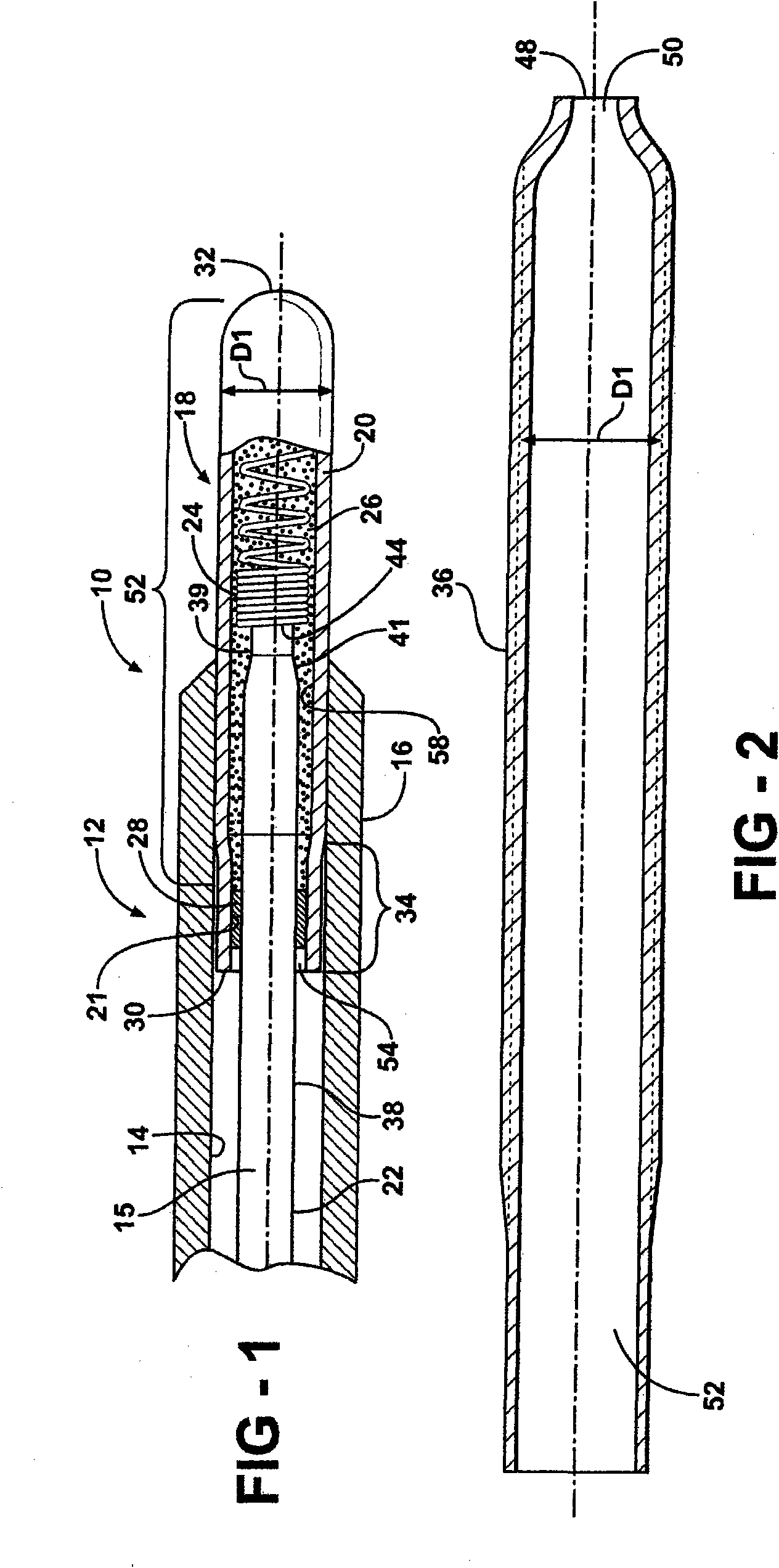
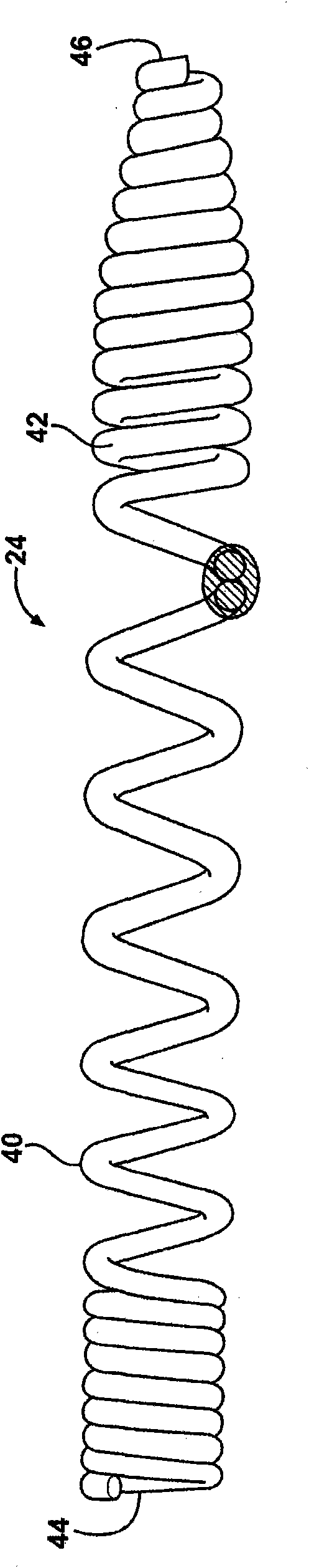
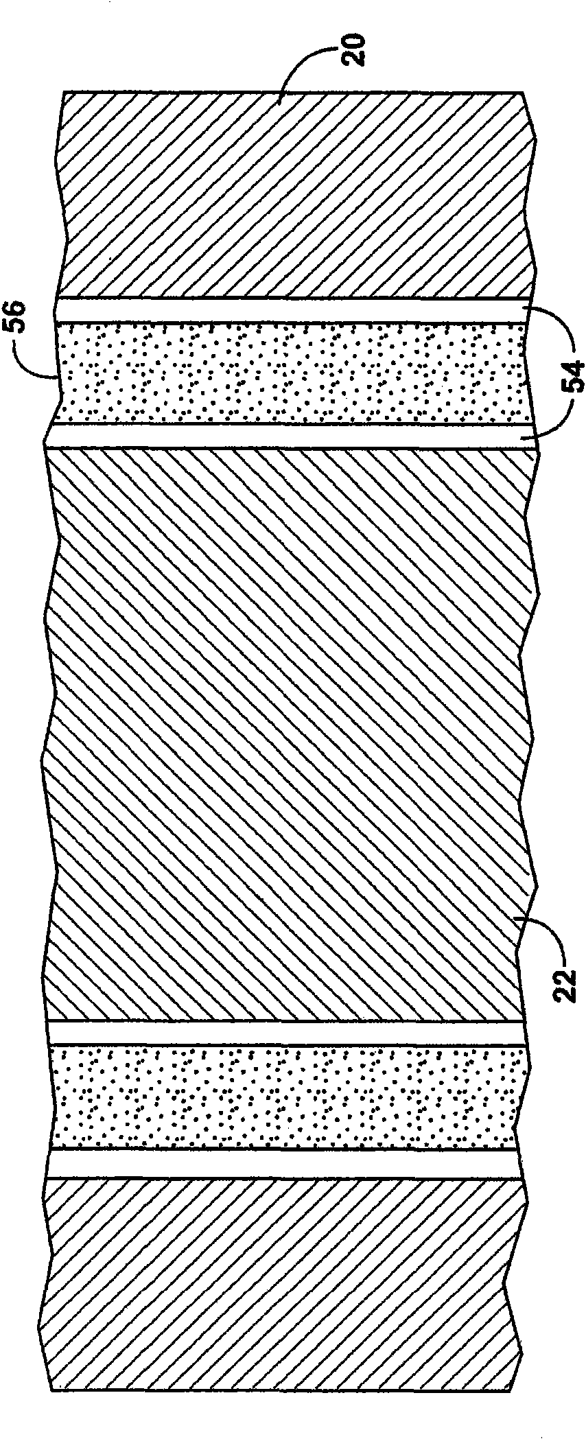
[0033] The present invention provides glow plugs with improved sealing and heating element assemblies that reduce the exposure of thermally conductive, electrically insulating powders and the helical wire heating elements embedded in the powders to oxygen and water vapor, thereby eliminating or substantially reducing the aforementioned the deterioration process. In the glow plug of the invention, the components are treated such that oxygen and water vapor within the powder layer are removed or substantially reduced during the mounting seal. Once installed, the seal eliminates or greatly reduces the ability of the surrounding atmosphere, including oxygen and water vapor, to penetrate the insulating powder and reach the resistance wire heating element, thereby inhibiting the potential for degradation of the resistance wire heating element as described above.

[0034] The glow plugs and glow plug heater assemblies of the present invention use glass or glass-ceramic seals instead ...


PUM

PropertyMeasurementUnit
thicknessaaaaaaaaaa
glass transition temperatureaaaaaaaaaa

Abstract

A glow plug which includes an annular metal shell, thermally conductive tubular sheath, central electrode; resistance heating element, and electrically insulating, thermally conductive powder includes a glass seal in sealing engagement with the sheath and the electrode to form a sealed cavity within the sheath. The glass seal may include silicate, borate and borosilicate glasses, and may include one or more transition metal oxides, such as oxides of chromium, cobalt, nickel, iron and copper. The glass may also include a filler, including a ceramic oxide, such as one selected from a group consisting of quartz, eucryptites, leucites, cordierites, beta-spodumene, glass-ceramics, low- expansion glass(CTE<5ppm / DEG C), mullite, zircon, zirconia and alumina. The sealed cavity may house a protective inert gas. The resistance heating element may be formed from a metal selected from a group consisting of tungsten, molybdenum, or alloys containing tungsten, molybdenum, nickel, iron, tantalum, niobium, titanium, vanadium, osmium and chromium.

Description

[0001] Cross References to Related Applications [0002] This patent application claims priority to US Provisional Application Nos. 61 / 014,122, filed December 17, 2007 and 61 / 061,387, filed June 13, 2008, the entire contents of which are incorporated herein by reference. technical field [0003] This invention relates generally to glow plugs, and more particularly to sheathed glow plugs. Background technique [0004] Sheathed glow plugs, such as those used in diesel engine applications, typically have a resistive heater comprising one or more resistive elements (such as helically wound resistive wire) embedded in an electrically insulating , thermally conductive powders, such as magnesium oxide, so as to be electrically insulated from the tubular sheath in which they are located, except for being electrically connected to a free closed end of the tubular sheath. Glow plugs employing a single resistive element may have a positive temperature coefficient characteristic (PTC ...

Claims


Application Information

Patent Timeline
Patent Type & Authority Applications(China)
IPC IPC(8): F23Q7/22F23Q7/00
CPCF23Q7/001
Inventor 约翰·霍夫曼桑德罗·葛莱蒂卡米洛·丽纳威廉·沃克马尔切洛·基诺
Owner FEDERAL MOGUL IGNITION
Why Eureka
Try Eureka