Chipless forming method for gear stick and section gear through hot extrusion

A technology of hot extrusion and gear rods, which is applied in the direction of metal extrusion dies, furnace types, heat treatment furnaces, etc., can solve the problems of tooth surface accuracy, low finish, large metal loss, and high quality of finished products, and achieve the effect of expanding energy saving and oxidation The effect of lightening and simplifying the production process

Inactive Publication Date: 2010-12-08
周家镳
View PDF0 Cites 30 Cited by
  • Summary
  • Abstract
  • Description
  • Claims
  • Application Information

AI Technical Summary

Problems solved by technology

There are basically two types of current gear processing methods: one is cutting gears with chips. Traditional processing methods such as turning, milling, drilling, slotting, and grinding have many procedures, low efficiency, and large metal loss. A large number of various gears are required. Processing machine tools and operators have high production costs; the second is chipless processing, such as warm extrusion and closed molding, which has high quality finished products and less metal loss, but the weight and shape of the blanks need to be accurately calculated, and the single production efficiency is very low. It is suitable for small batch production of gears with special requirements; another example is hot-rolled gears, which have the advantages of high efficiency and material saving, but the precision and finish of the tooth surface are low, and need to be ground. The cold-drawn gears are only used for non-ferrous metal processing.

Method used


Image

  • Chipless forming method for gear stick and section gear through hot extrusion
  • Chipless forming method for gear stick and section gear through hot extrusion
  • Chipless forming method for gear stick and section gear through hot extrusion

Examples


Embodiment Construction

[0033] The present invention will be further described in detail below in conjunction with the accompanying drawings and embodiments.

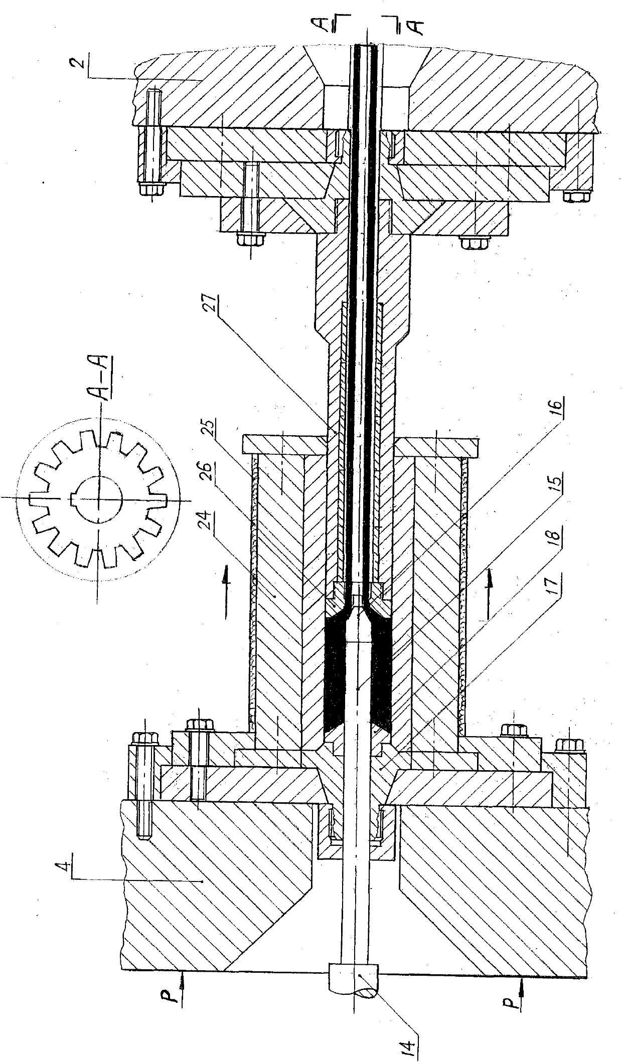
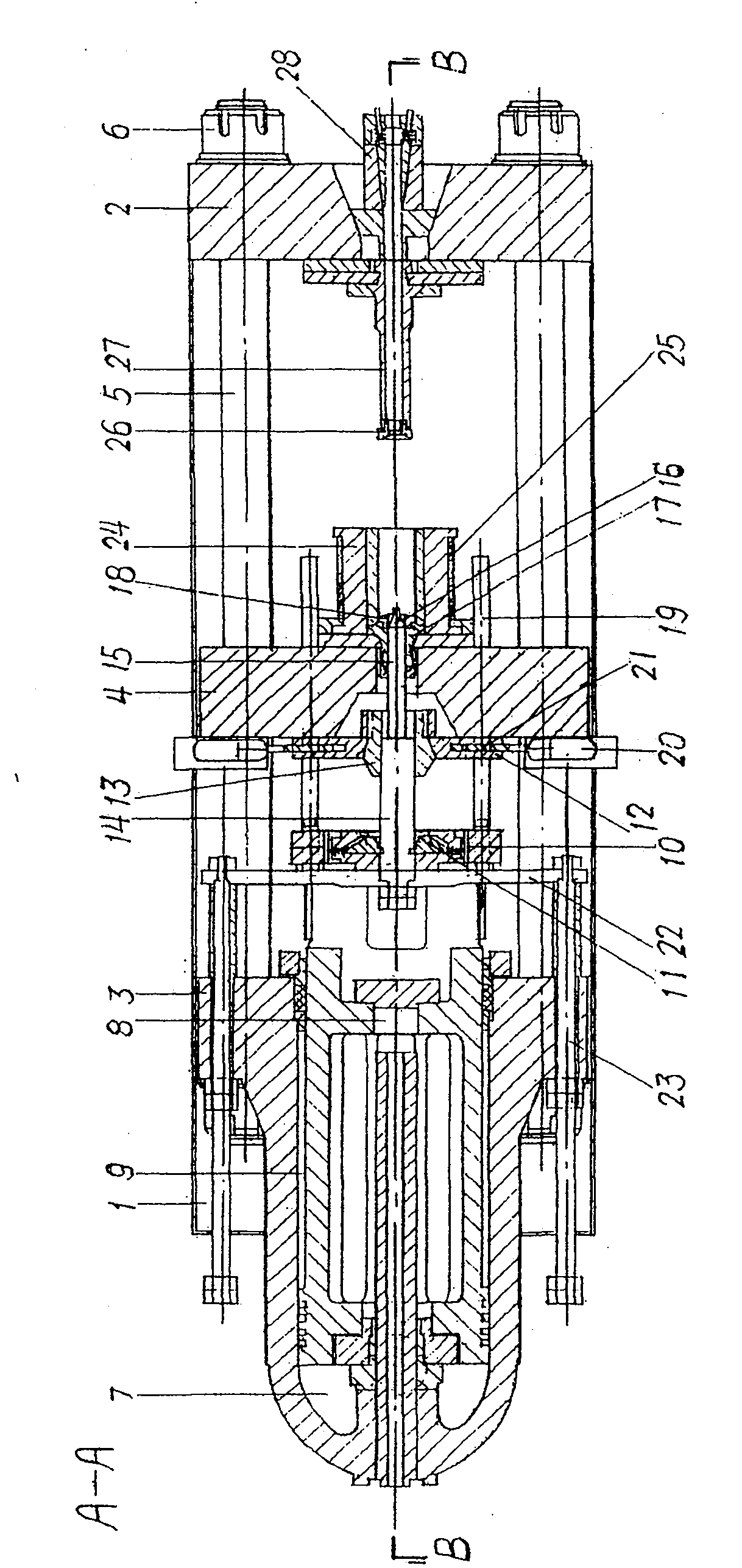
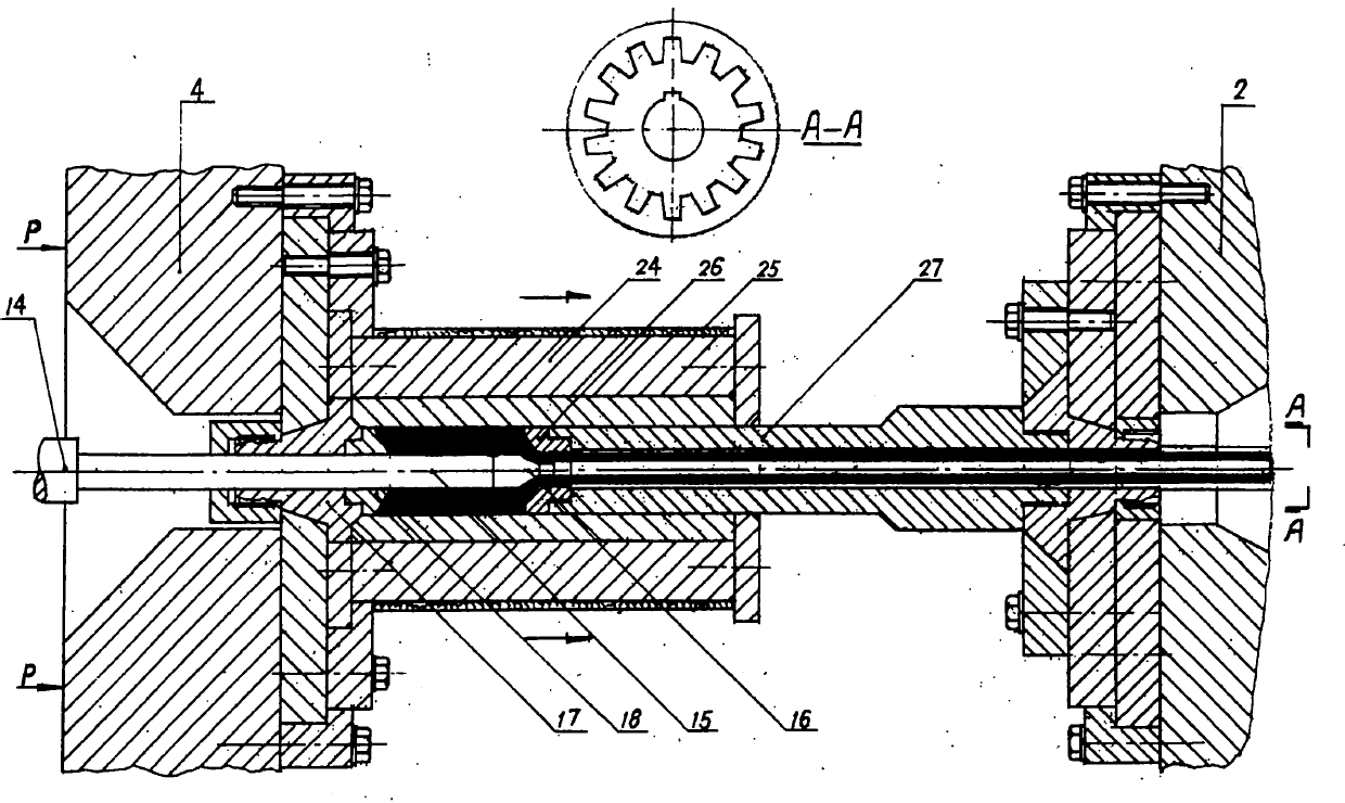
[0034] Such as Figure 1 to Figure 4 shows, the embodiment of the present invention, figure 1 It is a schematic diagram of the main structure of the converted FJH-1000 type one-time molding horizontal reverse hot extrusion machine, which is the key equipment carrier for implementing the present invention. The extruder body consists of machine base 1, front fixed beam 2, rear fixed beam 3, middle movable beam 4, tension column 5, nut 6, main hydraulic cylinder 7, mold transfer cylinder 8, return cylinder 9, etc.; The mold assembly of the automatic pressure switching operating system consists of a rear base plate assembly 10, a spring gate valve 11, a front base plate 12, a conical head 13, a main extrusion shaft 14, a mandrel 15, a perforating needle 16, a mandrel support 17 and an extrusion pad 18, The secondary shaft 19, the piston cylinder...


PUM


Abstract

The invention discloses a chipless forming method for a gear stick and a section gear through hot extrusion by utilizing an alloy steel horizontal type backward extruder, solving the problems that the existing gear cutting process has more working procedures, low efficiency, large metal loss, more operators for machine tool processing and high production cost and the like by utilizing the chip processes of lathing, milling, drilling, inserting and grinding. The method comprises the following steps: an inner cooling combined type double-conical surface gear squeezing die, a recipient and a floating pecker combined mandril are adopted by taking the producing principle of alloy steel thick wall special seamless steel tubes as an example; scale-free heating is rapidly carried out on the blank; lubricating warm-extrusion molding is carried out; center punching, shaft hole slotting and tooth surface extrusion are finished at a time; and the finished product of the gear stick is directly produced, then is subject to waste heat annealing, slicing by wire-electrode cutting and heating process to be manufactured into a finished product. Compared with a chip gear-cutting molding method, the invention has simplified working procedure, few labor, high efficiency, less metal loss, high gear strengthen and reduces the production cost, and then tooth surface precision reaches the standard. The method of the invention is a significant technological innovation of straight tooth and oblique tooth cylindrical gear process technologies.

Description

technical field [0001] The invention relates to the technical field of mechanical manufacturing gear processing, in particular to the chipless forming technology of hot extrusion gear rods and sliced ​​gears. Background technique [0002] Gears are common basic components of mechanical transmission, widely used and used in large quantities, and some of them are included in the finalized standard products. There are basically two types of current gear processing methods: one is cutting gears with chips. Traditional processing methods such as turning, milling, drilling, slotting, and grinding have many procedures, low efficiency, and large metal loss. A large number of various gears are required. Processing machine tools and operators have high production costs; the second is chipless processing, such as warm extrusion and closed molding, which has high quality finished products and less metal loss, but the weight and shape of the blanks need to be accurately calculated, and t...

Claims


Application Information

Patent Timeline
Patent Type & Authority Applications(China)
IPC IPC(8): B21C23/20B21C23/32B21C25/02B21C29/04C21D9/32B23P15/14
Inventor 周家镳
Owner 周家镳
Why Eureka
Try Eureka