
Combustion motor and stirling compound engine

A technology of Stirling engine and internal combustion engine, applied in the direction of internal combustion piston engine, combustion engine, machine/engine, etc., can solve the problems of low energy utilization rate, no power output of waste heat air conditioning technology, and complex system, so as to improve power performance. , compact structure, small volume effect

Inactive Publication Date: 2010-12-15
TIANJIN UNIV
View PDF6 Cites 14 Cited by
  • Summary
  • Abstract
  • Description
  • Claims
  • Application Information

AI Technical Summary

Problems solved by technology

However, each of these methods has its limitations
Supercharging technology can only use part of the energy of the exhaust gas, and the exhaust gas at the outlet of the turbine still has a high temperature, which has reuse value; waste heat air conditioning technology has no work output, and the energy utilization rate is low; thermoelectric power generation is limited by materials With the development of other technologies, the efficiency of thermoelectric conversion is low; the use of Rankine cycle to recover the energy of exhaust gas, the system is complicated, and the volume and weight are difficult to meet the requirements
The structure of the Stirling engine is compact, but the efficiency of the currently used Stirling engine to recover the waste heat of the exhaust gas of the internal combustion engine is still low. The proposal of the present invention can make the waste heat of the internal combustion engine more fully utilized, improve the thermal efficiency of the engine, and significantly reduce the heat loss of the engine. Improve fuel consumption and improve engine power

Method used


Image

  • Combustion motor and stirling compound engine
  • Combustion motor and stirling compound engine
  • Combustion motor and stirling compound engine

Examples


Embodiment Construction

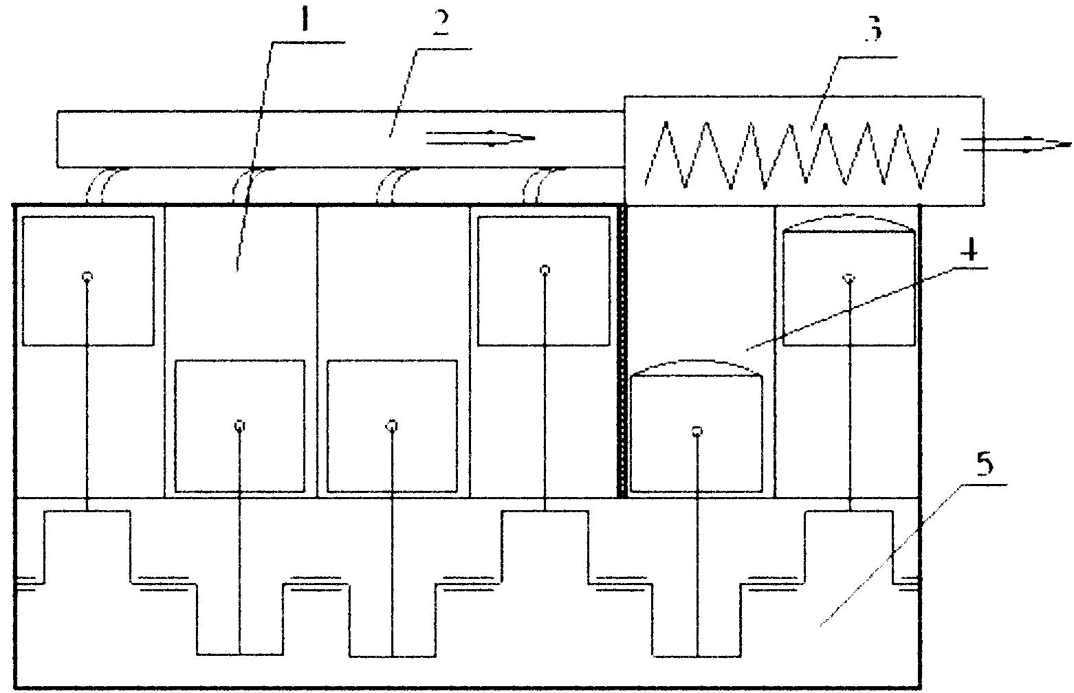
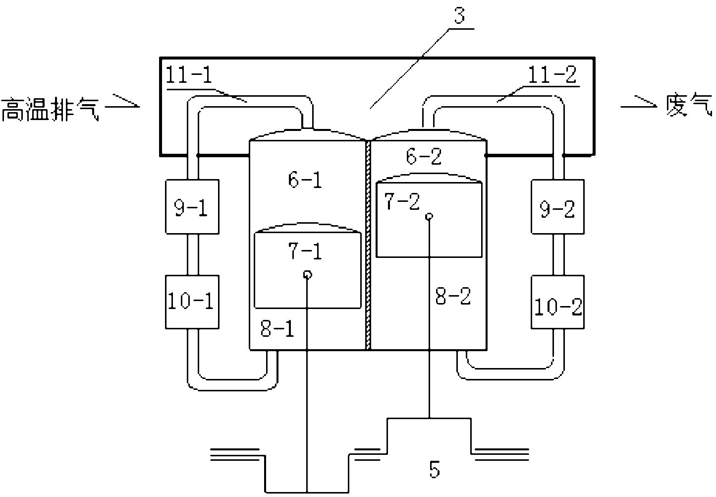
[0010] The present invention will be further described below in conjunction with accompanying drawings and examples. Structurally, the internal combustion engine 1 and the Stirling engine 4 are combined into one body, the exhaust pipeline 2 of the internal combustion engine 1 is connected in series with the heater 3 of the Stirling engine, and the exhaust gas of the internal combustion engine is used as a high-temperature heat source of the Stirling engine 4, The same crankshaft 5 is driven by the power generated by the two systems of internal combustion engine 1 and Stirling engine 4 (such as figure 1 ). After the high-temperature exhaust gas is transferred to the working medium of the Stirling engine through the heater, the low-temperature exhaust gas is discharged to the atmosphere. The working fluid in the Stirling engine passes through two identical closed loops (such as figure 2 ), the circulating working medium can be hydrogen or helium. The first circulation loop i...


PUM


Abstract

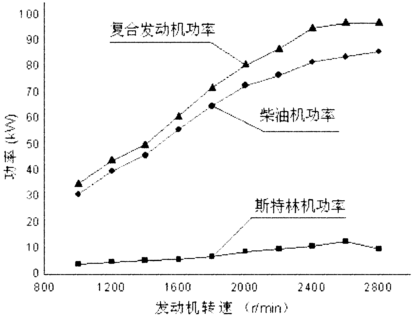
The invention relates to an engine compounded by combustion motor and stirling engine. Combustion motor and stirling engine are in the same machine body, the exhaust pipe of the combustion motor is connected with the heater of the stirling enging in series, exhaust of the combustion motor is taken as high temperature heat source of the stirling engine, and power produced by the two engines is used for driving the same crankshaft. Working medium in the stirling engine passes through closed circulation loops, each loop is composed of an expanding cavity, a piston, a compression cavity, a heat regenerator, a cooler and a group of heating tubes which are sequentially connected. The processes of working medium when doing work in the circulation loop are the same, namely the working medium absorbs heat of exhaust of the combustion motor and then is expanded in the expanding cavity, the piston is driven to move downward, and the crankshaft is driven to do work. The invention has the characteristic that stirling engine can absorb waste heat of exhaust of combustion motor to the utmost extent. Compared with the traditional combustion motor waste heat recycling device, the invention can cause mean effective power of diesel engine to be increased by 10% under the same fuel consumption condition.

Description

technical field [0001] The invention belongs to engine technology, in particular to an engine composed of an internal combustion engine and a Stirling engine. Background technique [0002] With the shortage of petroleum energy and the stricter emission regulations, the issue of energy conservation and emission reduction has attracted more and more attention. Finding high-efficiency, non-polluting energy, promoting the secondary utilization of energy, and researching methods of energy recovery and conversion are all effective ways to reduce energy waste and improve energy utilization. Only about 1 / 3 of the energy generated by the combustion of fuel in internal combustion engines is effectively utilized, and the rest is lost to the atmosphere, and nearly 1 / 3 of the energy is lost by exhaust gas. Therefore, the effective use of the exhaust gas energy of the internal combustion engine is a powerful measure to save energy, reduce emissions, and improve the thermal efficiency of ...

Claims


Application Information

Patent Timeline
IPC IPC(8): F01N5/02F02G1/044F02G1/055
CPCY02T10/16Y02T10/12
Inventor 高文志谢必鲜冯黎明韦慧勇边强张晶
Owner TIANJIN UNIV
Learn More