
Bus technology-based universal electromagnetic susceptibility testing device and method

A technology of electromagnetic susceptibility and testing equipment, applied in the direction of measuring equipment, bus network, electromagnetic field characteristics, etc., can solve the problems of huge cost and effort, inconvenient expansion and update of the electromagnetic susceptibility testing system, and achieve security assurance and easy expansion Effect

Inactive Publication Date: 2010-12-15
BEIHANG UNIV
View PDF2 Cites 29 Cited by
  • Summary
  • Abstract
  • Description
  • Claims
  • Application Information

AI Technical Summary

Problems solved by technology

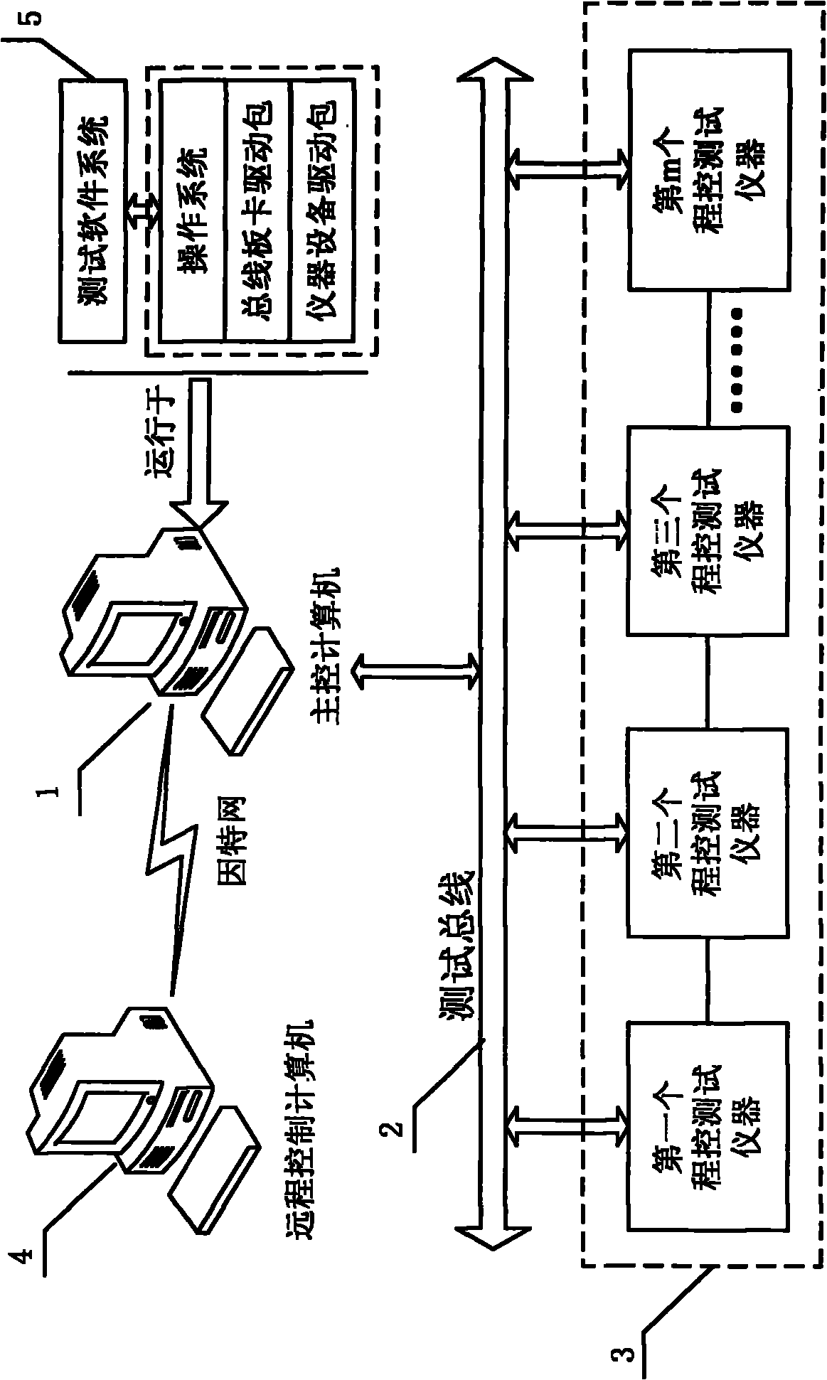
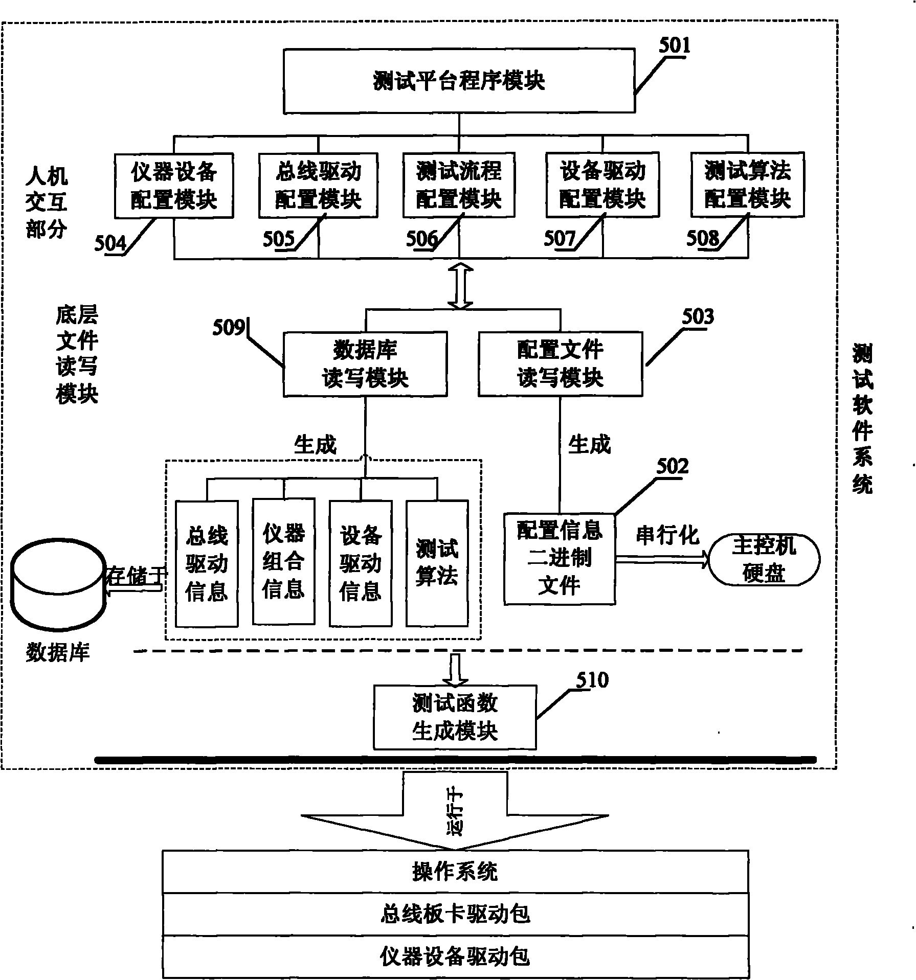
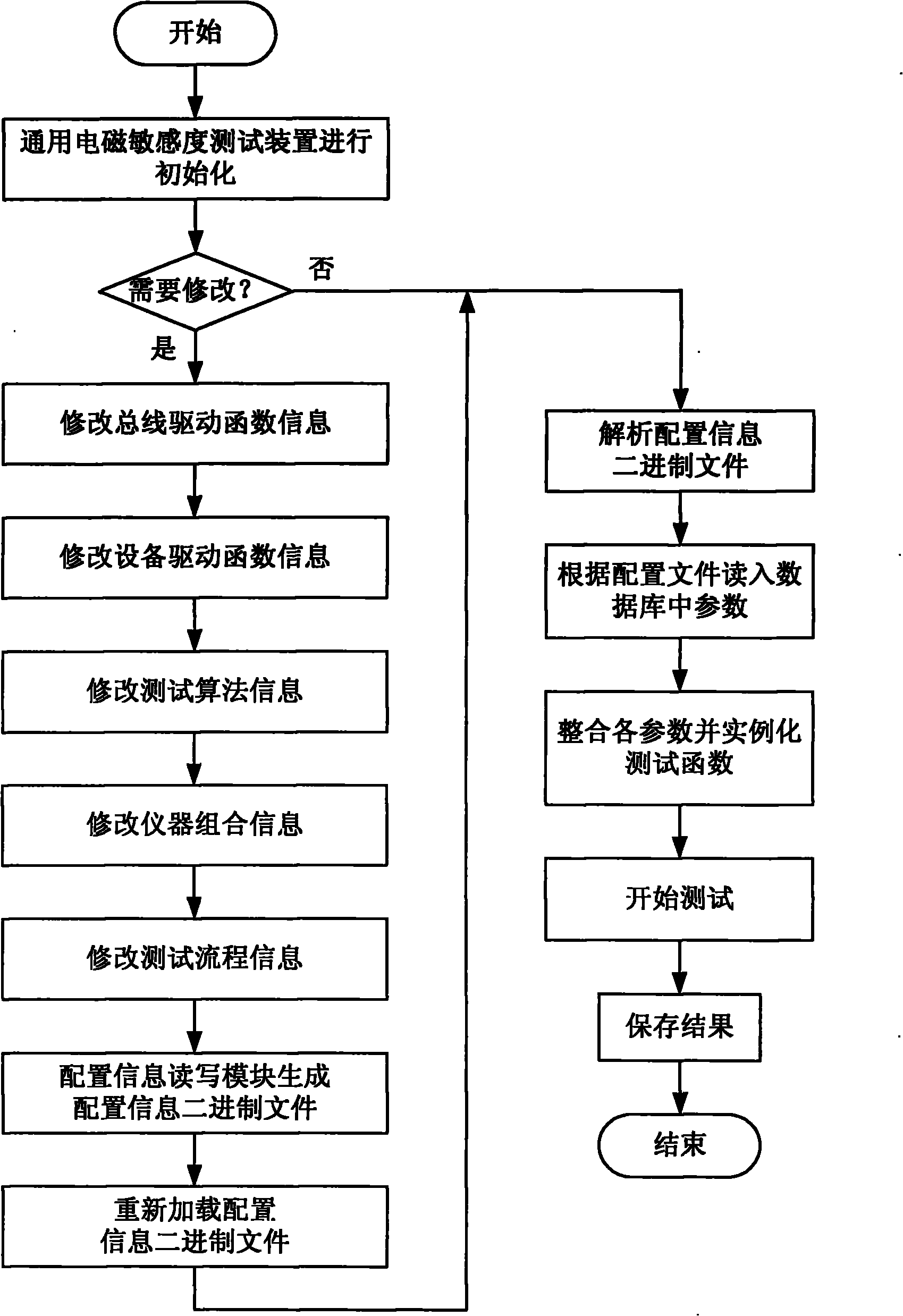
[0004] The purpose of the present invention is to solve the problem that the existing electromagnetic susceptibility test system requires huge cost and effort to redesign in terms of function expansion and algorithm update, and provides a general electromagnetic susceptibility test device based on bus technology, which drives the bus Information, device driver information, test algorithm information, instrument combination information and test process information are separated from the upper test platform program. The user modifies the above information according to the actual parameters of the electromagnetic susceptibility test system, and the test platform program dynamically loads these parameters. The electromagnetic susceptibility test device can easily expand the function, add nodes or update the test algorithm only by modifying the configuration information, which solves the problem that the current electromagnetic susceptibility test system is not easy to expand and update

Method used


Image

  • Bus technology-based universal electromagnetic susceptibility testing device and method
  • Bus technology-based universal electromagnetic susceptibility testing device and method
  • Bus technology-based universal electromagnetic susceptibility testing device and method

Examples


Embodiment

[0094] Figure 4 It is a typical electromagnetic susceptibility test circuit in a certain frequency band. The main control computer 1 is equipped with a PCI-GPIB board to drive the GPIB bus. At the same time, the main control computer 1 has a 9pin serial interface based on RS232 for the field strength The monitor 304 communicates and reads the current field strength value. The signal source 301 is used to generate a test signal, mostly a sinusoidal signal. The generated signal needs to be sent to the power amplifier 302 for signal amplification due to its weak power. The amplified signal is sent to the transmitting antenna 303, and the transmitting antenna 303 transmits the sent signal The energy radiates out to form a radiation field in the darkroom, and the DUT is tested for sensitivity in this radiation field. The field strength monitor probe 305 is the sensitive measuring element of the field strength monitor 304, and it is in the darkroom facing the transmitting antenna 3...


PUM


Abstract

The invention discloses a bus technology-based universal electromagnetic susceptibility testing device and a bus technology-based universal electromagnetic susceptibility testing method. The testing device comprises a main control computer, a program control testing instrument, a remote control computer and a testing software system. The testing method comprises the following steps of: 1, initializing the universal electromagnetic susceptibility testing device; 2, setting parameters aiming at the electromagnetic susceptibility test by a user; 3, starting an upper level test platform program to start the test; and 4, testing a function generation module-instantiated test function, and testing the electromagnetic susceptibility. The invention overcomes the defect of redesign of the conventional electromagnetic susceptibility testing system when new equipment, the type of a testing bus or the connection mode of the testing instrument needs to be replaced or a testing algorithm needs to be updated, realizes the universal electromagnetic susceptibility testing system with convenient function expansion, addition of node equipment and update of the testing algorithm, and reduces the cost and the energy for system expansion and maintenance.

Description

technical field [0001] The invention relates to a general electromagnetic susceptibility testing device and testing method based on bus technology, belonging to the field of computer measurement and control. Background technique [0002] As a resource, electromagnetic waves have been widely used in the wide frequency range from very low frequency to microwave band. However, the accompanying electromagnetic interference is pervasively radiated or conducted to the operating electronic equipment, systems and the surrounding environment. . In military aviation and aerospace systems, including missile or rocket launching spacecraft devices, the electromagnetic compatibility and reliability of the entire system play a very important role. Various components, subsystems and full systems are subjected to extensive Electromagnetic Susceptibility (EMS) testing prior to system assembly and configuration. [0003] However, the current electromagnetic susceptibility test systems are ge...

Claims


Application Information

Patent Timeline
Patent Type & Authority Applications(China)
IPC IPC(8): G01R29/08G01R31/00H04L12/40
Inventor 王青王昭磊王明明周怀平董朝阳
Owner BEIHANG UNIV
Learn More