Single-optical fiber scanning micro device as well as production method and control method thereof

A single-fiber, micro-device technology, applied in the field of optical scanning, can solve problems such as difficult processing, and achieve the effect of reducing computing time

Active Publication Date: 2010-12-22
JINGWEI SHIDA MEDICAL TECH WUHAN CO LTD
View PDF1 Cites 26 Cited by
  • Summary
  • Abstract
  • Description
  • Claims
  • Application Information

AI Technical Summary

Problems solved by technology

Existing piezoelectric scanning structures mainly use quadrant electrode tubes and piezoelectric bimorphs, both of which are difficult to process into micro-sized
Moreover, the quadrupole scanner requires four driving voltages, and the piezoelectric bimorph can only vibrate in one dimension.

Method used


Image

  • Single-optical fiber scanning micro device as well as production method and control method thereof
  • Single-optical fiber scanning micro device as well as production method and control method thereof
  • Single-optical fiber scanning micro device as well as production method and control method thereof

Examples


Embodiment 1

[0053] Embodiment 1: Fabrication of single-fiber scanning micro-device

[0054] In this example, the materials used to make the single-fiber scanning micro-device are: four thin ceramic strips, single-mode optical fiber, conductive glue, superglue, and five thin wires.

[0055] 1. Take four piezoelectric ceramic sheets with a length of 8 mm, a width of 1.2 mm, and a thickness of 0.5 mm, coated with silver electrode layers on both sides;

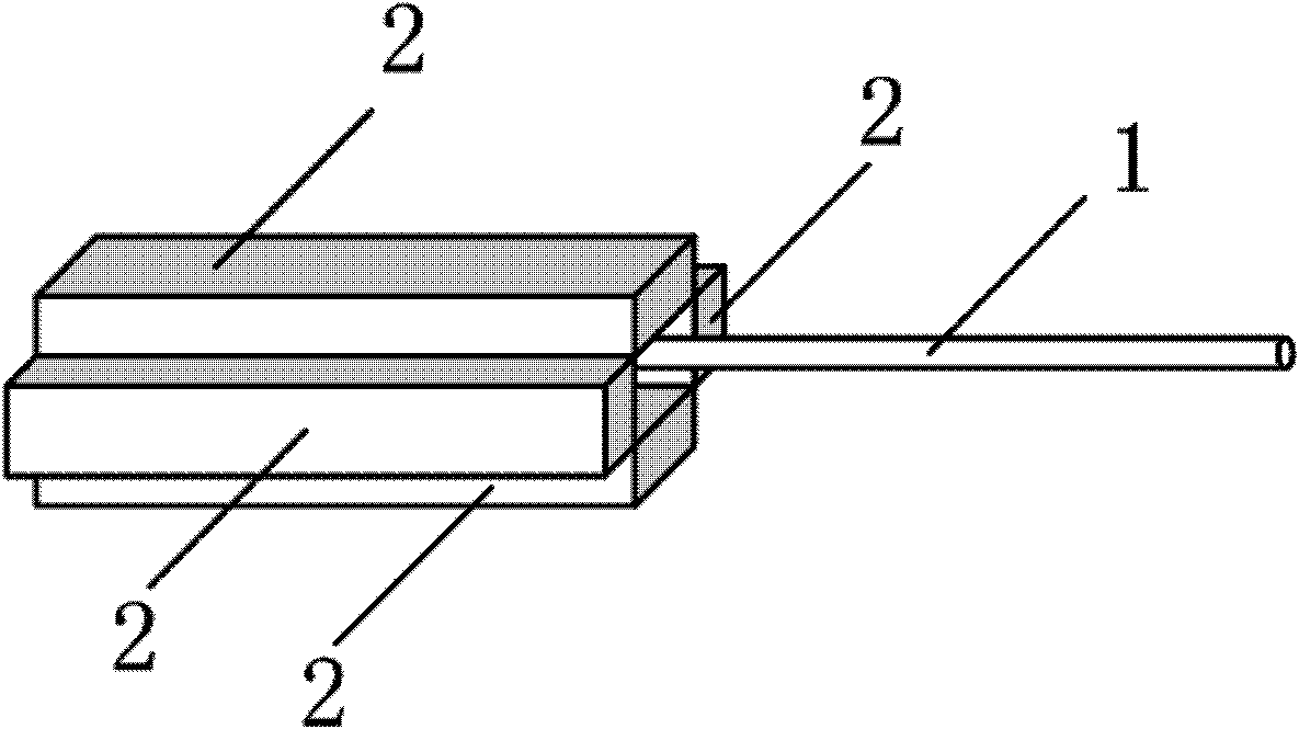
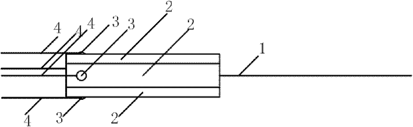
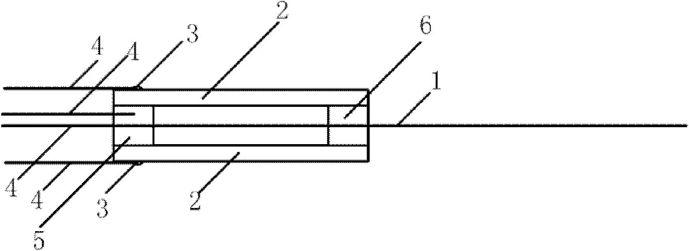
[0056] 2. Remove the 15mm coating from the end of a single-mode optical fiber to expose the bare optical fiber, cut the end face of the optical fiber flat with a fiber cutter, place the optical fiber in the gap between two piezoelectric ceramic sheets, and reserve a length of 10mm (the resonance frequency is about 1kHz) as the vibration free end;

[0057] 3. Four pieces of ceramics surround the cavity, and the two opposite piezoelectric ceramics have the same polarization direction. Place the optical fiber and a wire on the axis of the cera...

Embodiment 2

[0059] Embodiment 2: Finite element analysis of single-fiber scanning micro-device

[0060] Such as Figure 5 , 6 As shown in , 7 and 8, the structural dynamics analysis of the single-fiber scanning micro-device under the electromechanical coupling field is carried out by using the finite element method. The analysis results can predict and fully verify the dynamics of the micro-device during the scanning process with high precision. characteristic.

[0061] The finite element analysis of the single-fiber scanning micro-device realized in this embodiment includes:

[0062] Modal Analysis: Analyze the natural frequencies of a structure. Provides a reference for the applied drive signal frequency.

[0063] Harmonic response analysis: Obtain the scanning amplitude of the scanner under the sine wave driving signal of each frequency. The driving signal to be applied can be determined under different scanning requirements;

[0064] Transient analysis: It is possible to determi...

Embodiment 3

[0071] Embodiment 3: Voltage-driven control of single-fiber scanning micro-device

[0072] As shown in 9, 10, and 11, the probe is driven by two signals. The driving signal adopts a sine wave modulated by a sine wave, which can be scanned in a spiral mode. The carrier frequency is the natural frequency of the fiber cantilever, and the modulation wave frequency corresponds to the scanning frame rate. The phases of the modulated waves of the two signals are the same, and the carrier waves differ by 90°. If the ceramic pair performs simple harmonic vibration with the same frequency and the same amplitude with a difference of 90° in both horizontal and numerical directions, the fiber scanning trajectory is a circle. If the amplitude increases and decreases repeatedly at a certain frequency, a helical trajectory can be obtained. The modulated sine wave of 1 / 4 cycle corresponds to one frame of image (that is, a spiral signal from inside to outside) during scanning, that is, the m...


PUM

PropertyMeasurementUnit
radiusaaaaaaaaaa

Abstract

The invention relates to a single-optical fiber scanning micro device as well as a production method and a control method thereof. The single-optical fiber scanning micro device is formed by wrapping an optical fiber with four pieces of piezoelectric ceramics, wherein a coating at the tail end of the optical fiber is removed, both ends of the four piezoelectric ceramics blocks are bonded around the optical fiber, a section of naked optical fiber is reserved, the four pieces of piezoelectric ceramics form a square cavity, the outer walls of the four pieces of piezoelectric ceramics are respectively provided with leads by tin soldering, the inner walls of the four pieces of piezoelectric ceramics on the cavity are conducted by conductive adhesives and are provided with one lead, the conducing wires of the two opposite pieces of ceramics in the horizontal direction are connected, and the leads of the two opposite pieces of ceramics in the vertical direction are connected. The single-optical fiber scanning micro device produced by the method has the advantages of short length, small size, good scanning repeatability, easy obtainment of raw materials, easy processing and low manufacturing cost, thereby having favorable application prospects on optical precise instruments as well as illumination devices, signal collection device and other devices in the field of clinical endoscopic operations.

Description

technical field [0001] The invention belongs to the technical field of optical scanning, and relates to a single optical fiber scanning micro device, a preparation method and a control method. Background technique [0002] Optical instruments based on micro-scanning devices have important application prospects in the fields of industrial flaw detection, micro-displacement sensing, and medical imaging technology. Commonly used optical scanning devices include: optical scanning galvanometers, micro-rotating motors, micro-opto-electromechanical systems, acousto-optic deflectors, polygonal prism rotating systems, and piezoelectric ceramics. In existing scanning devices, the optical scanning galvanometer and the multi-faceted prism rotating system are relatively bulky and cannot be built into the endoscopic probe. Tiny rotating motors can only be imaged sideways. Micro-opto-electromechanical systems are complex and expensive to manufacture. The volume of the acousto-optic defl...

Claims


Application Information

Patent Timeline
Patent Type & Authority Applications(China)
IPC IPC(8): G02B26/10
Inventor 付玲骆清铭曾绍群李智杨哲
Owner JINGWEI SHIDA MEDICAL TECH WUHAN CO LTD
Why Eureka
Try Eureka