

Grinding composite for planarization metal layer
A technology of composition and metal layer, applied in polishing compositions containing abrasives, etc., can solve problems such as slowing down the etching rate
- Summary
- Abstract
- Description
- Claims
- Application Information
AI Technical Summary
Problems solved by technology
Method used
Image

Examples
Embodiment 1-5
[0022] According to list in table 1, use the abrasive slurry composition that comprises silica sol abrasive grain, glycine, hydrogen peroxide, 1-H-benzotriazole (BTA), 1,2,4-triazole and water Implement samples for testing.
[0023] Table 1
[0024]
[0025] The grinding test was performed under the following conditions.
[0026] Grinding machine table: Mirra polisher (Applied Materials)
[0027] Wafer type: 8”, 15KA Copper blanket wafer (Ramco Co)
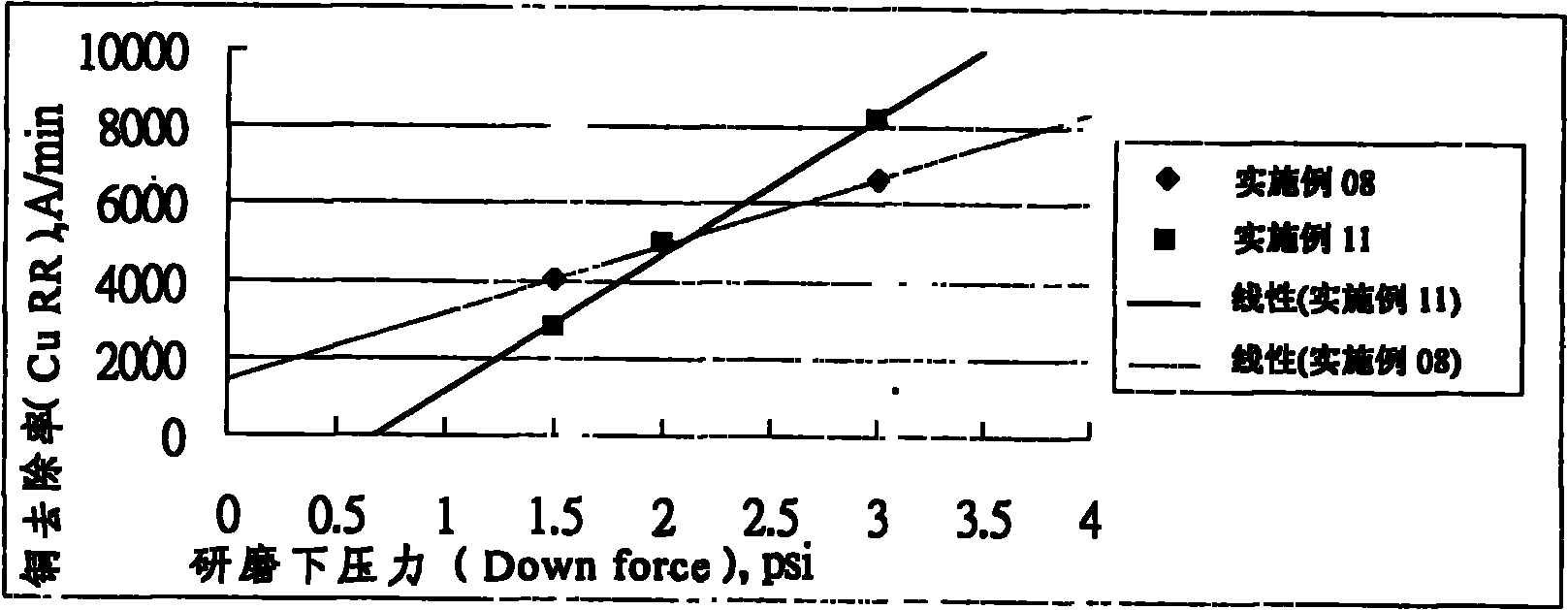
[0028] Grind Downforce: 3, 1.5 and 0psi
[0029] Platform speed: 93rpm
[0030] Vehicle speed: 87rpm
[0031] Polishing pad: IC 1010 (Rohm Hass Electronic Materials)
[0032]Slurry flow rate: 150ml / min.
[0033] The wafer uses a 4-point probe to measure the thickness of the copper film before and after grinding to calculate the rate. The results are shown in Table 2:
[0034] Table 2
[0035]
[0036]
[0037] Wherein, the RR refers to the grinding removal rate (Removal Rate), and the DER refers to the dynamic et...
Embodiment 5-6
[0040] According to list in table 3, use the abrasive slurry composition that comprises silica sol, glycine, hydrogen peroxide, 1-H-benzotriazole (BTA), 1,2,4-triazole and water Implement samples for testing.
[0041] table 3
[0042]
[0043] The grinding test was carried out according to the following conditions, and the results are recorded in Table 4.
[0044] Wafer type: MIT854 patterned wafer (Ramco Co)
[0045] Grinding Downforce: 3psi
[0046] Platform speed: 93rpm
[0047] Vehicle speed: 87rpm
[0048] Slurry flow rate: 150ml / min.
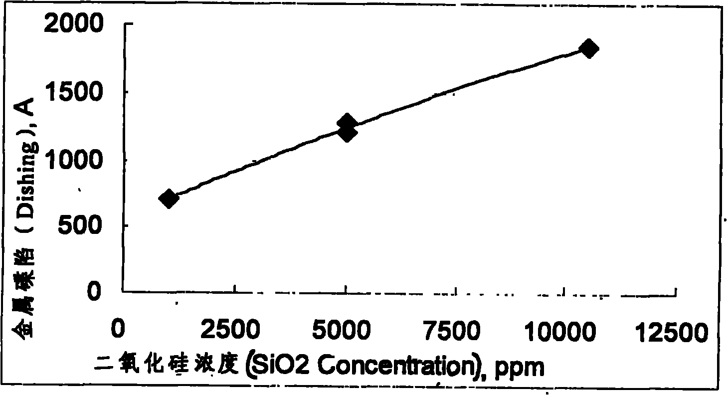
[0049] Use the HRP220profiler (KLA-Tenco) instrument to measure the degree of metal disc sinking at each measurement point after grinding. During the measurement, a 100x100 micron copper wire is used as the measurement point, and the results of measuring the crystal grains at the center, middle and edge of the wafer are recorded in the table. 4:
[0050] Table 4
[0051]
[0052] These metal disc sinking values are 30% over...
Embodiment 7-13
[0054] As listed in Table 5, the test was performed using a control sample of abrasive composition comprising silica sol abrasive grains, glycine, hydrogen peroxide, benzotriazole, 1,2,4-triazole and water.
[0055] table 5
[0056]
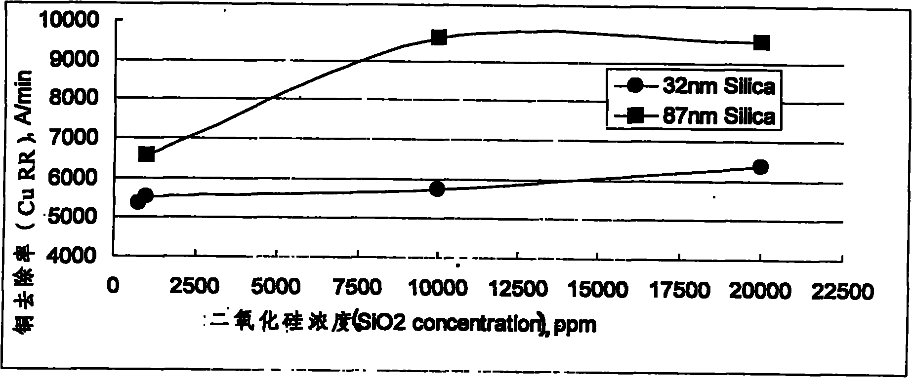
[0057] Each embodiment of Table 5 is on the grinding machine platform of Mirra polisher (Applied Materials), and carries out grinding test according to the condition listed in embodiment 1-5, and the wafer of grinding has Cu, Ta and TaN Blanket wafers, and its The results are shown in Table 6, and figure 1 :
[0058] Table 6
[0059]
[0060]
[0061] According to the results in Table 6, it can be seen that the higher the abrasive particle concentration, the higher the copper grinding removal rate, and this phenomenon is more obvious when the abrasive particle size is larger; and when the abrasive particle concentration reaches a certain content, the grinding removal rate will decrease. When reaching a flat area, it will no longer ris...
PUM
 Abstract
Description
Claims
Application Information