Heat preservation composite wall provided with meshed plaster on two sides

A thermal insulation composite and wall technology, applied in thermal insulation, building thermal insulation materials, walls, etc., can solve the problems of inconvenient installation of anti-theft fences and heavy decorations, affecting the energy saving and thermal insulation effect of composite walls, and difficulty in achieving low heat transfer coefficients. It can achieve the effect of energy saving and heat preservation, good fire prevention and anti-seismic effect.

Inactive Publication Date: 2011-01-05
吴淑环
View PDF2 Cites 24 Cited by
  • Summary
  • Abstract
  • Description
  • Claims
  • Application Information

AI Technical Summary

Problems solved by technology

Even if 20-30mm of insulation strips are pasted on the outside of the hole, the linear heat transfer coefficient ψ value can reach 0.1w/m.k, which is not good for energy saving and heat preservation, and it is difficult to achieve a low heat transfer coefficient
[0011] The thermal bridge at the opening is also a serious problem in the wall energy-saving and heat-preservation t

Method used


Image

  • Heat preservation composite wall provided with meshed plaster on two sides
  • Heat preservation composite wall provided with meshed plaster on two sides
  • Heat preservation composite wall provided with meshed plaster on two sides

Examples


specific Embodiment approach 1

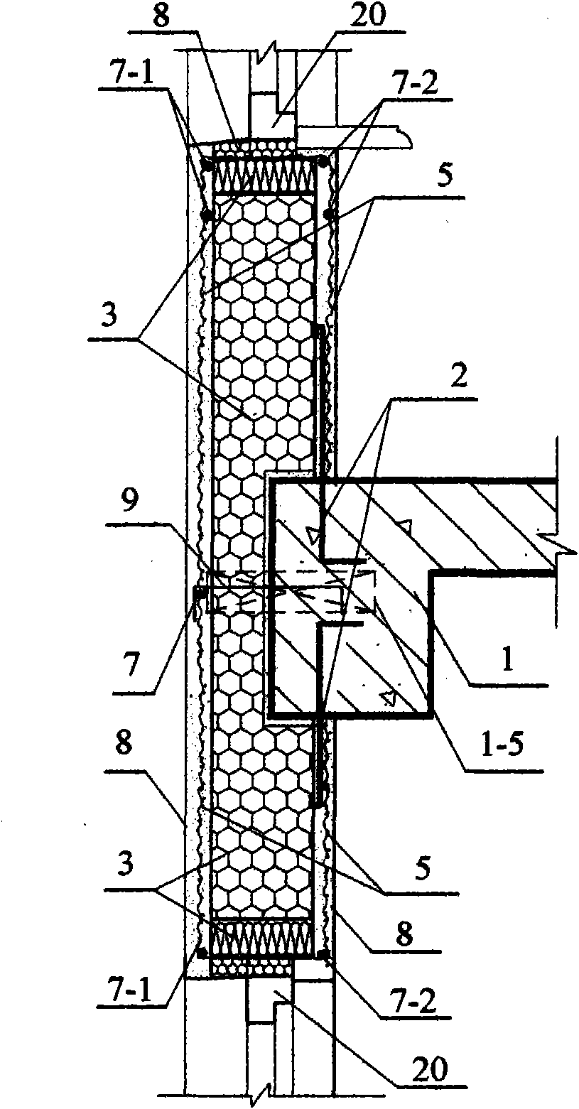
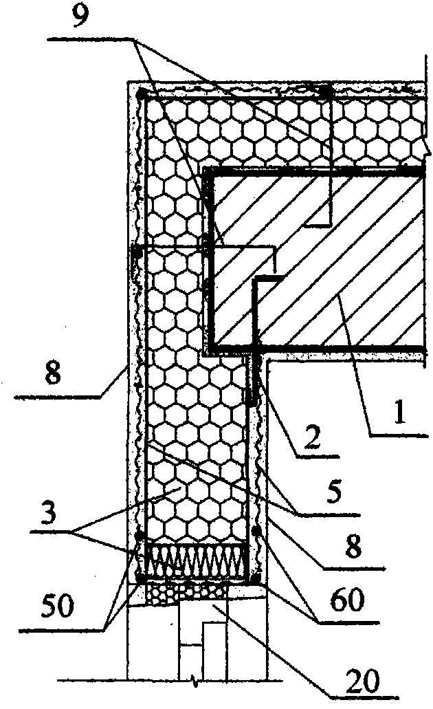
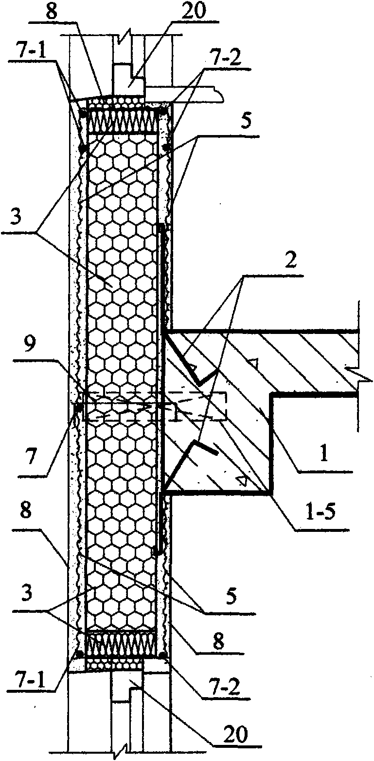
[0057] Specific implementation mode one: see Figure 1 to Figure 12 , Figure 14 , a thermal insulation composite wall with net plastering on both sides of this embodiment is composed of a load-bearing member 1 of the main building structure, a short anchoring steel bar 2, a core layer 3, a mesh tensile material 5, doors and windows 20, and outdoor vertical steel bars 50. Indoor vertical steel bars 60, outdoor horizontal additional steel bars 7-1, indoor horizontal steel bars 7-2, protective layer 8, and supporting cantilever beams 1-5; the load-bearing member 1 of the main structure of the building is a beam (including the foundation Beam), board (including base plate), column, load-bearing wall; the core layer 3 is polymer insulation material, or mineral wool or plant straw or paper honeycomb board or insulation mortar; the mesh tensile material 5 is Alkali-resistant mesh cloth 5-1 or metal mesh 5-2 or bamboo reinforcement mesh 5-3; the protective layer 8 is cement mortar o...

specific Embodiment approach 2

[0067] Specific implementation mode two: see Figure 5 ~ Figure 7 The difference between this embodiment and the specific embodiment one is: this embodiment increases the waterproof and moisture-proof layer 15; the waterproof and moisture-proof layer 15 has the following three installation methods: 1), the waterproof and moisture-proof layer 15 is directly pasted on the core layer of the hole 3, or the waterproof and moisture-proof layer 15 wraps the core layer 3 of the hole, and the doors and windows 20 are installed on the waterproof and moisture-proof layer 15; 2), alkali-resistant mesh cloth 5-1 is pasted on the surface of the hole core layer 3, and the waterproof and moisture-proof layer 15 is pasted Above the alkali-resistant mesh cloth 5-1, the doors and windows 20 are installed on the waterproof and moisture-proof layer 15; 3), the waterproof and moisture-proof layer 15 is pasted on the core layer 3, or the waterproof and moisture-proof layer 15 wraps the core layer 3 o...

specific Embodiment approach 3

[0070] Specific implementation mode three: see Figure 1 ~ Figure 4 , Figure 9~ Figure 12 The difference between this embodiment and the specific embodiment one or two is: this embodiment increases the internal and external tension connection steel wire 9; the inner end of the internal and external tension connection steel wire 9 is anchored in the load-bearing member 1 of the main structure of the building, and the outer end is connected to the outdoor Vertical reinforcement 50 is connected, or the outer end is connected with the outdoor horizontal additional reinforcement 7-1, or the outer end is connected with the outdoor mesh tensile material 5; -1 or the outdoor mesh tensile material 5 is connected to the indoor vertical steel bar 60, the indoor horizontal steel bar 7-2 or the indoor mesh tensile material 5.

[0071] The inner and outer drawing connecting steel wires 9 can be Φ2.5 or Φ3 stainless steel drawing connecting steel wires, the stainless steel wires are soft, ...


PUM


Abstract

The invention provides a heat preservation composite wall provided with meshed plaster on two sides, relates to heat preservation composite walls of buildings, and aims to solve the problem that heat bridges of openings of an energy-saving wall affect the building energy conservation. The heat preservation composite wall comprises a main building structure load-carrying member, short anchoring steel bars, a core layer, a meshed tensile material, outdoor vertical steel bars, indoor vertical steel bars, a supporting cantilever beam piece, outdoor horizontal additional steel bars, indoor horizontal steel bars, doors, windows and protective layers, wherein the short anchoring steel bars and the indoor vertical steel bars are anchored with the main building structure load-carrying member; the outdoor vertical steel bars are fixed with the supporting cantilever beam piece; the outdoor horizontal additional steel bars are fixed with the outdoor vertical steel bars; the outdoor vertical steel bars are fixed with the indoor vertical steel bars; the core layer is fixed between the outside and the inside of a frame; two sides of the core layer are provided with the protective layers; the short anchoring steel bars are overlapped with the meshed tensile material; the doors and the windows are arranged on the core layer; and two sides of the doors and the windows are provided with the protective layers. As the openings of the heat preservation composite wall provided with the meshed plaster on the two sides have a heat insulation broken bridge structure, the energy saving and heat preservation effect of walls is greatly improved.

Description

technical field [0001] The invention relates to a thermal insulation composite wall body of a building, in particular to a thermal insulation composite wall body with mesh plastering on both sides. Background technique [0002] 1. The thermal bridge at the opening of doors and windows is the bottleneck of energy-saving and thermal insulation technology for barrier walls [0003] At present, the best thermal insulation effect in a large number of applications in our country is to paste EPS board thin plaster insulation wall, but the fire prevention is not good, the durability is not good, and the outer surface is not safe. But at present, even if the EPS board with the best thermal insulation is thinly plastered to insulate the wall, since the insulation layer pasted around the opening of the door and window is much thinner than the facade of the wall, more heat will be lost on the side wall of the opening. The "65% Design Standard for Energy Saving of Residential Buildings ...

Claims


Application Information

Patent Timeline
IPC IPC(8): E04B2/00E04B1/76E04B1/64
CPCE04B1/7629F16B5/01E04B2/90Y02A30/00Y02B30/90
Inventor 吴淑环
Owner 吴淑环
Why Eureka
Try Eureka