Mixed refrigerant and nitrogen expansion combinational refrigeration type natural gas liquefying method

A technology of mixing refrigerant and natural gas, applied in refrigeration and liquefaction, liquefaction, recovery of liquid hydrocarbon mixture, etc., can solve the problem of high purity requirements of pure refrigerant components, difficult configuration of refrigerant component proportions, and large volume flow of gaseous refrigerants and other problems, to achieve the effect of low refrigerant composition requirements, reduction of operation labor intensity, and reduction of equipment volume

Active Publication Date: 2011-01-19
CHINA NAT OFFSHORE OIL CORP +2
View PDF3 Cites 31 Cited by
  • Summary
  • Abstract
  • Description
  • Claims
  • Application Information

AI Technical Summary

Problems solved by technology

The nitrogen expansion refrigeration process is simple, but the efficiency is low, and it can only be used in small-scale liquefaction devices such as peak-shaving type; the cascade refrigeration process has high efficiency, and since the three refrigeration cycles are all pure components, design calculation and operation comparison It is convenient, but the process equipment and compressor units are many, the purity requirements of the pure components of the refrigerant are high, the heat exchange equipment is many and complex, and the equipment investment is high; the single mixed refrigerant process is simple, and the efficiency is higher than that of the cascade refrigeration process Low, because there is only one refrigeration cycle, and the pressure of gaseous refrigerant after throttling is low, so the volume flow rate of gaseous refrigerant is large, and it is limited by compressors, cold boxes and other equipment when it is applied to medium to large devices, so it is generally only used in For small and medium-si

Method used


Image

  • Mixed refrigerant and nitrogen expansion combinational refrigeration type natural gas liquefying method
  • Mixed refrigerant and nitrogen expansion combinational refrigeration type natural gas liquefying method
  • Mixed refrigerant and nitrogen expansion combinational refrigeration type natural gas liquefying method

Examples


Embodiment

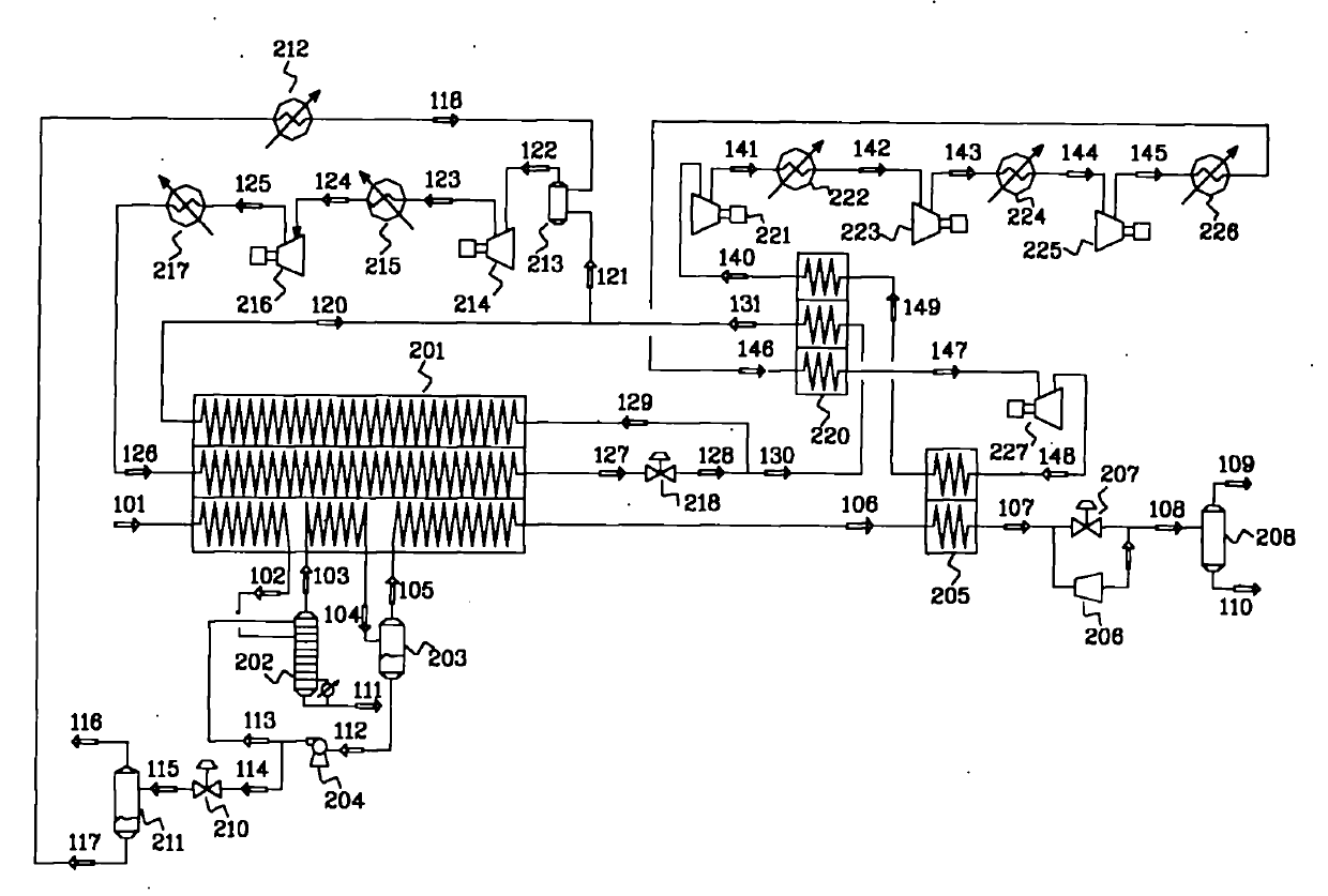
[0010]The process and device system involved in this embodiment includes a mixed refrigerant refrigeration unit, a mixed refrigerant compression unit, a nitrogen expansion refrigeration unit, a nitrogen compression unit, a heavy hydrocarbon removal unit, and a mixed refrigerant preparation supplementary unit; the main body of the device used includes Liquefaction section cold box 201, subcooling section cold box 205, nitrogen heat exchanger 220, LNG J-T valve 207, liquid expander 206, LNG storage tank 208, mixed refrigerant J-T valve 218, mixed refrigerant buffer tank 213, mixing Refrigerant primary compressor 214, mixed refrigerant primary cooler 215, mixed refrigerant secondary compressor 216, mixed refrigerant secondary cooler 217, nitrogen primary compressor 221, nitrogen primary cooler 222, nitrogen Secondary compressor 223, nitrogen secondary cooler 224, nitrogen tertiary compressor 225, nitrogen tertiary cooler 226, nitrogen expander 227, heavy hydrocarbon removal tower ...


PUM


Abstract

The invention belongs to the technical field of gas liquefaction and relates to a mixed refrigerant circulation and nitrogen expansion circulation combinational refrigeration type natural gas liquefying method. The method comprises the following steps of: allowing natural gas subjected to pretreatments such as acid gas removal, dehydration and the like to enter a natural gas liquefying section cooling box; performing refrigeration by vaporizing the mixed refrigerant in the liquefying section cooling box and controlling the pressure to be 4 to 10 Mpa so as to liquefy the natural gas under high pressure, wherein the temperature of the liquefied natural gas (LNG) departing from the liquefying section cooling box is between -75 and -110 DEG C; cooling the LNG to about -150 DEG C after the LNGenters a supercooling section cooling box; reducing pressure to be the pressure of a storage tank by using a liquid expander and further cooling to about -160 DEG C; and then compressing the LNG to serve as fuel gas. The method has the advantages of simple technical process, high reliability, high liquefaction rate and suitability for industrialized production.

Description

technical field [0001] The invention belongs to the technical field of gas liquefaction, and relates to a natural gas liquefaction process, in particular to a refrigeration type natural gas liquefaction method using a mixed refrigerant cycle and a nitrogen expansion cycle. Background technique [0002] At present, the processes used for natural gas liquefaction at home and abroad mainly include: nitrogen expansion refrigeration process, cascade refrigeration process, single mixed refrigerant process, mixed refrigeration process with propane pre-cooling, and double mixed refrigerant process. Each has its own advantages and disadvantages. The nitrogen expansion refrigeration process is simple, but the efficiency is low, and it can only be used in small-scale liquefaction devices such as peak-shaving type; the cascade refrigeration process has high efficiency, and since the three refrigeration cycles are all pure components, design calculation and operation comparison It is co...

Claims


Application Information

Patent Timeline
IPC IPC(8): C10L3/10C10G5/06
CPCF25J1/0022F25J1/0042F25J1/005F25J1/0052F25J1/0072F25J1/0215F25J1/0238F25J1/025F25J1/0265F25J2220/62F25J2220/64
Inventor 张道光金海刚王俊美卜晓玲陈广明李琴刘红波杨福昌
Owner CHINA NAT OFFSHORE OIL CORP
Why Eureka
Try Eureka