Electrolytic electric spark cutting composite micromachining device and method

A micro-machining and EDM technology, applied in the direction of manufacturing tools and other manufacturing equipment/tools, etc., can solve the problems of small machining depth-to-diameter ratio, overcutting phenomenon and thermal influence, low material removal rate, etc., and achieves high machining accuracy, The method is simple and practical, and the effect of low cost

Inactive Publication Date: 2011-02-16
SHANGHAI JIAO TONG UNIV
View PDF5 Cites 30 Cited by
  • Summary
  • Abstract
  • Description
  • Claims
  • Application Information

AI Technical Summary

Problems solved by technology

However, electrolytic EDM also has disadvantages, such as low material removal rate, overc

Method used


Image

  • Electrolytic electric spark cutting composite micromachining device and method
  • Electrolytic electric spark cutting composite micromachining device and method
  • Electrolytic electric spark cutting composite micromachining device and method

Examples


Embodiment Construction

[0027] The embodiments of the present invention are described in detail below. This embodiment is implemented on the premise of the technical solution of the present invention, and detailed implementation methods and specific operating procedures are provided, but the protection scope of the present invention is not limited to the following implementation example.

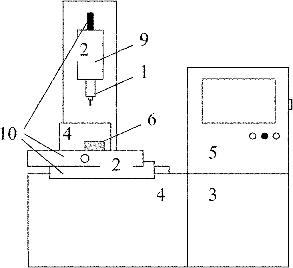
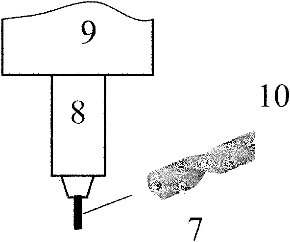
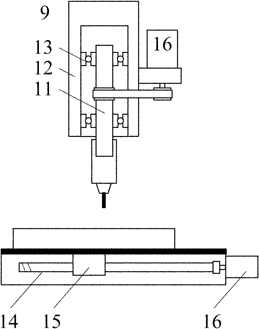
[0028] like figure 1 As shown, this embodiment includes: a tool system 1, a mechanical motion system 2, a power supply system 3, a working fluid system 4 and a control system 5, wherein: the tool system 1 is installed on the rotating spindle 9 of the mechanical motion system 2, and the mechanical motion system The three linear moving axes 10 of 2 drive the rotation of the tool and the relative movement between the tool and the workpiece 6 to be processed. The control system 5 is connected with the mechanical motion system 2 and outputs work instructions, and drives the mechanical motion system 2 to complete the mai...


PUM


Abstract

The invention relates to electrolytic electric spark cutting composite micromachining device and method in the technical field of mechanical manufacture. The electrolytic electric spark cutting composite micromachining device comprises a cutter system, a mechanical movement system, a power supply system, a working solution system and a control system. On the basis of the traditional non-conducting material electrolytic electric spark machining technology, the invention introduces cutting machining by utilizing physical contact characteristics of a machining electrode and a non-conducting workpiece to be machined so that the cutting machining becomes new electrolytic electric spark cutting composite micromachining. The composite machining method overcomes the defects of machining efficiency, machining precision, and the like of the traditional electrolytic electric spark machining method and improves the machinability of difficult machining materials, such as glass, ceramics, and the like.

Description

technical field [0001] The invention relates to a device in the field of mechanical manufacturing technology and a processing method thereof, in particular to an electrolytic electric spark cutting composite micro-machining device and a processing method thereof. Background technique [0002] Non-conductive materials such as glass, ceramics, and composite materials are widely used in the fields of micro-electro-mechanical systems, micro-fluidic systems, biomedicine, and aerospace. Some examples in engineering include micro-reactors, micro-pumps, human implant components, etc. These materials are often brittle, hard and non-conductive, making them difficult to process. Especially in micro-machining, the commonly used micro-EDM cannot handle these non-conductive materials; mechanical processing methods, such as micro-milling, micro-grinding, etc., are also difficult to handle due to the hard and brittle materials, and the material removal rate during processing is very low. ...

Claims


Application Information

Patent Timeline
IPC IPC(8): B23P23/00B23H5/00
Inventor 魏臣隽倪军许开州胡德金许黎明
Owner SHANGHAI JIAO TONG UNIV
Why Eureka
Try Eureka