Metallurgical furnace dedusting waste heat recovery machine and method

A waste heat recovery and recovery method technology, applied in separation methods, chemical instruments and methods, furnaces, etc., can solve problems such as system equipment blockage, large dust volume, waste heat boiler ash blocking, etc., to reduce construction costs, operating costs, and dust emissions. The effect of low concentration and improved heat exchange efficiency

Inactive Publication Date: 2011-03-30
无锡市曜通环保机械有限公司
View PDF0 Cites 5 Cited by
  • Summary
  • Abstract
  • Description
  • Claims
  • Application Information

AI Technical Summary

Problems solved by technology

[0003] 1. Dust removal after heat exchange of the mechanical cooler: the cooling effect is poor, the temperature of the imported flue gas should not be greater than 500°C, the cooling range is limited, and the tube wall of the mechanical cooler is easy to be blocked with ash, resulting in burning cloth bags and the system cannot operate normally
[0004] 2. Dust removal after spray cooling and heat exchange: increasing the water content in the flue gas will not only harden the bag, but also easily cause water and dust to bond, resulting in blockage of system equipment
[0005] 3. Dust removal after heat exchange of the waste heat boiler: Since the flue gas contains a large amount of dust, the sticky and fine dust will accumulate dust and blockage even on the heat pipe elements of the light pipe. Ash and clogging are more serious. At the

Method used


Image

  • Metallurgical furnace dedusting waste heat recovery machine and method
  • Metallurgical furnace dedusting waste heat recovery machine and method
  • Metallurgical furnace dedusting waste heat recovery machine and method

Examples


Embodiment Construction

[0020] The present invention will be further described below in conjunction with accompanying drawing.

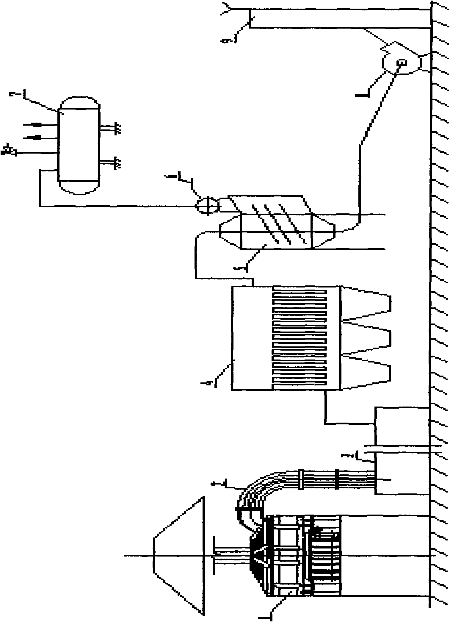
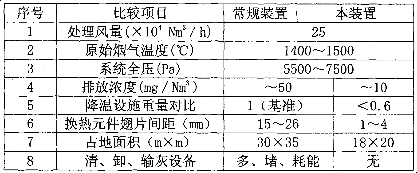
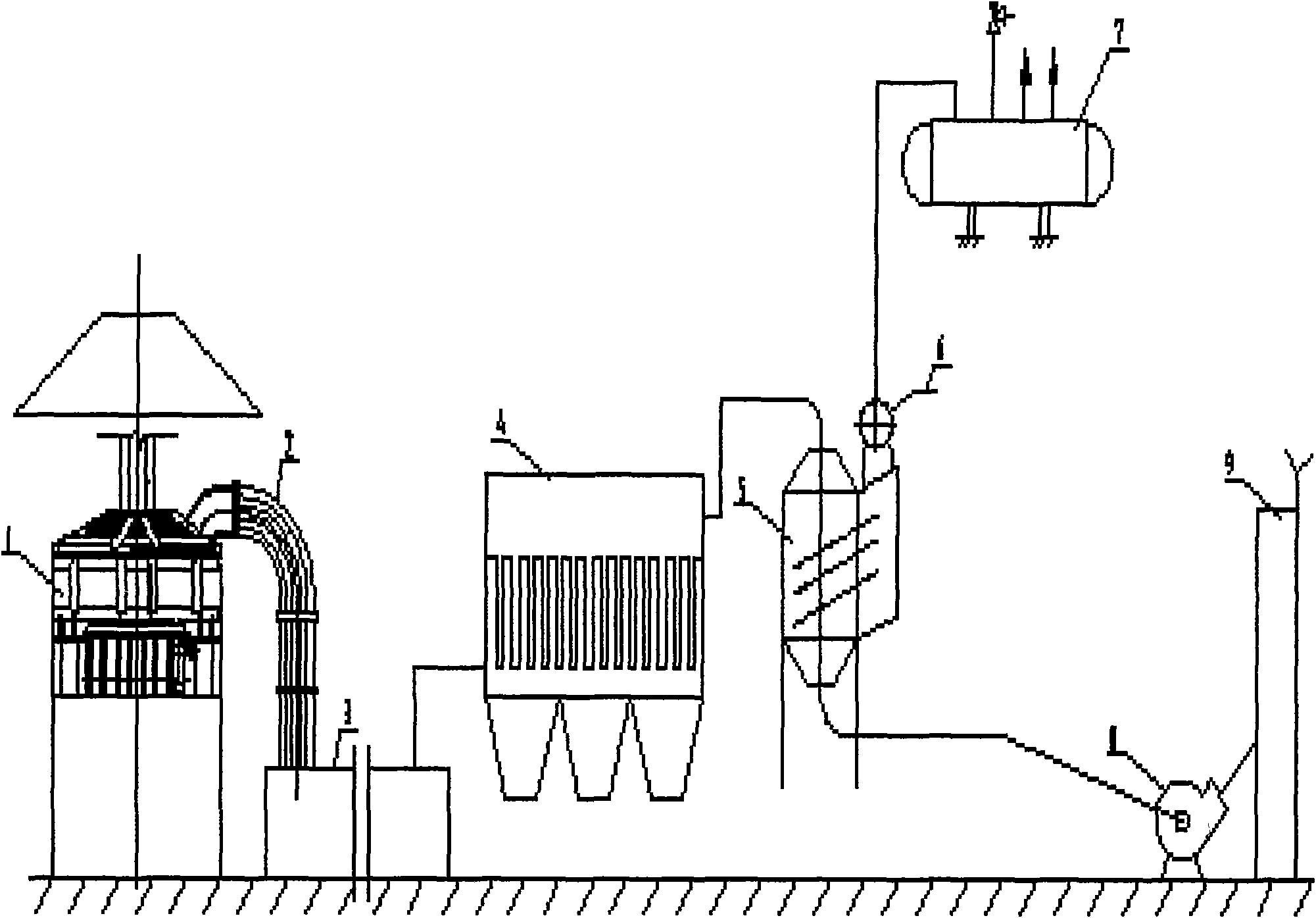
[0021] A 90t / h steelmaking electric furnace waste heat recovery adopts this method, such as figure 1 As shown, the exhaust gas in the electric furnace (1) is discharged from the fourth hole, mixed with cold air through the four-hole water-cooled sliding sleeve (2), and enters the combustion and settling chamber (3) after burning carbon monoxide gas; the effect of the burning and settling chamber (3) is : Reduce the flue gas flow rate, settle the large particles of dust carried in the flue gas, and properly mix it with cold air, finally burn the carbon monoxide gas, and adjust the outlet flue gas temperature to not exceed 1500°C; the flue gas from the combustion and settling chamber (3) enters Ceramic filter element dust collector (4), the dust concentration after dust removal is less than 10mg / Nm 3 . Then it enters the finned tube heat pipe heat exchanger (5) to complete ...


PUM


Abstract

The invention relates to a metallurgical furnace dedusting waste heat recovery machine and a metallurgical furnace dedusting waste heat recovery method. A technical scheme is that: the metallurgical furnace dedusting waste heat recovery machine comprises high-temperature smoke generating equipment, a draught fan and an exhaust cylinder which are connected with one another sequentially through pipelines. A waste heat utilization facility is placed behind a dust catcher, and the dust content of heat source smoke is low and is not taken into consideration when the equipment is designed and manufactured, so the space between heat exchange core unit fins can be designed to be small and dust-unloading, dust-cleaning and dust-conveying facilities are unnecessary; and the volume of the waste heat utilization facility is reduced, so the maintenance quantity of the waste heat utilization facility is reduced and the service life of the waste heat utilization facility is prolonged.

Description

Technical field [0001] The invention belongs to the field of dust removal waste heat recovery of metallurgical furnaces, and relates to dust removal and waste heat recovery of metallurgical furnace flue gas. Background technique [0002] Metallurgical furnace (electric furnace, converter, rotary hearth furnace) steelmaking flue gas temperature is very high, after being captured, the temperature entering the pipeline is generally around 1500 °C, and the dust concentration is up to 25g / Nm 3 , The ash less than 10um accounts for more than 70% of the total amount of dust, the amount of dust is large, and it is sticky and fine. At present, the method of heat exchange and cooling is usually adopted first (heat exchange and cooling methods include: mechanical cooler heat exchange, spray cooling heat exchange, waste heat boiler heat exchange, etc.) and then dust removal method. There are many disadvantages in the method of heat exchange and cooling before dust removal: [0003] 1....

Claims


Application Information

Patent Timeline
IPC IPC(8): F27D17/00B01D46/00B01D39/20
CPCY02P10/25Y02P80/15
Inventor 顾云红
Owner 无锡市曜通环保机械有限公司
Why Eureka
Try Eureka