
Reactor for producing phenyl chlorosilane by using thermal poly-condensation method

A phenylchlorosilane and reactor technology, which is applied in the field of reactors for preparing phenylchlorosilane, can solve the problems of carbon deposition in the bed, low production efficiency, complicated by-product magnesium chloride and solvent treatment, etc., so as to avoid damage and reaction smooth effect

Active Publication Date: 2011-04-20
ZHEJIANG KAIHUA SYNTHETIC MATERIAL
View PDF5 Cites 3 Cited by
  • Summary
  • Abstract
  • Description
  • Claims
  • Application Information

AI Technical Summary

Problems solved by technology

The process is simple and the raw materials are easy to obtain; its disadvantages are: the preparation process of the formatted reagent has high requirements, and sometimes improper control during the reaction process may easily cause punching or explosion; the by-product magnesium chloride and solvent treatment are more complicated; the production efficiency is low; With the emergence of the direct method, the format method has basically been eliminated
Its disadvantages: the amount of catalyst copper is 30-50% (mass ratio) of the amount of silicon powder, and the amount of catalyst is relatively large; the by-products contain polychlorinated biphenyls, which are highly toxic and carcinogenic
In this method, there are many side reactions of materials in the system, and the by-product polychlorinated biphenyl carcinogens are generated. The silicon powder wears the equipment greatly, and there is a phenomenon of periodic equipment replacement, and there is carbon accumulation in the bed, which requires frequent periodic maintenance. equipment

Method used


Image

  • Reactor for producing phenyl chlorosilane by using thermal poly-condensation method
  • Reactor for producing phenyl chlorosilane by using thermal poly-condensation method
  • Reactor for producing phenyl chlorosilane by using thermal poly-condensation method

Examples


Embodiment Construction

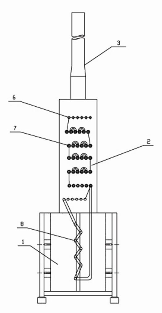
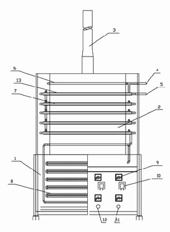
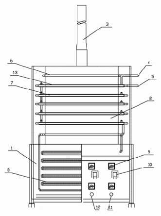
[0023] As shown in the figure, the reactor for producing phenylchlorosilane by thermal condensation method of the present invention includes the reactor body. The reactor body is provided with a radiation zone 1 (ie heating section) at the lower part of the body and a convection zone 2 (ie reaction section) at the middle of the body. A chimney 3 is also arranged on the upper part of the reactor body. The heating section furnace tube 8 is arranged in the radiation area 1, and the entire radiation area 1 is in a rectangular shape as a whole. In actual use, it can be designed as the following dimensions according to the needs: length: 6000mm, width: 4000mm, height: 4000mm or length: 7500mm, Width: 5000mm, height: 5000mm or length: 9000mm, width: 6000mm, height: 6000mm. Due to the design of the above dimensions, the heat radiation space of the radiation zone 1 is more suitable and the radiation effect is better. There are also flameless burners 9 and flame observation holes 10 o...


PUM


Abstract

The invention discloses a reactor for producing phenyl chlorosilane by using a thermal poly-condensation method. The reactor comprises a reactor body, wherein a radiation zone positioned below the reactor body and a convective zone positioned in the middle of the reactor body are arranged in the reactor body; the upper part of the reactor body is also provided with a chimney; a heating section furnace tube is arranged in the radiation zone; a reaction section furnace tube is arranged in the convective zone; a jacket is arranged on the periphery of the reaction section furnace tube; a raw material preheating furnace tube used for recovering smoke gas heat is also arranged at the junction of the chimney and the convective zone; one end of the raw material preheating furnace tube is provided with a raw material inlet; the raw material preheating furnace tube is communicated with the jacket; the jacket is communicated with the radiation section furnace tube; the tail end of the radiation section furnace tube is communicated with the reaction section furnace tube; and the tail end of the reaction section furnace tube is provided with a material outlet. The reactor for producing the phenyl chlorosilane has a simple structure and a safe and energy-saving effect.

Description

technical field [0001] The invention belongs to the field of chemical equipment, in particular to a reactor for preparing phenylchlorosilane. Background technique [0002] At present, there are three methods for producing phenylchlorosilane, which are the Grizzard method, the direct method and the condensation method. [0003] Method 1: format method. Using chlorobenzene and trichlorosilane or methyl dichlorosilane as raw materials, using Grignard reagent as catalyst, adding a certain amount of solvent, and controlling a certain temperature and pressure to produce phenylchlorosilane products. The process is simple and the raw materials are easy to obtain; its disadvantages are: the preparation process of the formatted reagent has high requirements, and sometimes improper control during the reaction process may easily cause punching or explosion; the by-product magnesium chloride and solvent treatment are more complicated; the production efficiency is low; With the emergenc...

Claims


Application Information

Patent Timeline
Patent Type & Authority Applications(China)
IPC IPC(8): B01J8/00C07F7/12
CPCY02P20/10
Inventor 魏涛廖端友汪玉林郑云峰
Owner ZHEJIANG KAIHUA SYNTHETIC MATERIAL
Learn More