
Uninterrupted chemical battery

A chemical battery and battery technology, applied in the electronics industry, chemical industry, electric power, electrosynthesis industry, mining and metallurgy fields, can solve the problems of power consumption and waste, and achieve the effect of reducing energy consumption

Inactive Publication Date: 2011-04-27
NO 63971 TROOPS PLA
View PDF0 Cites 2 Cited by
  • Summary
  • Abstract
  • Description
  • Claims
  • Application Information

AI Technical Summary

Problems solved by technology

Therefore, the consumption and waste of electric energy has become a bottleneck for the further development of the electrosynthesis industry

Method used


Image

  • Uninterrupted chemical battery
  • Uninterrupted chemical battery
  • Uninterrupted chemical battery

Examples


example 1

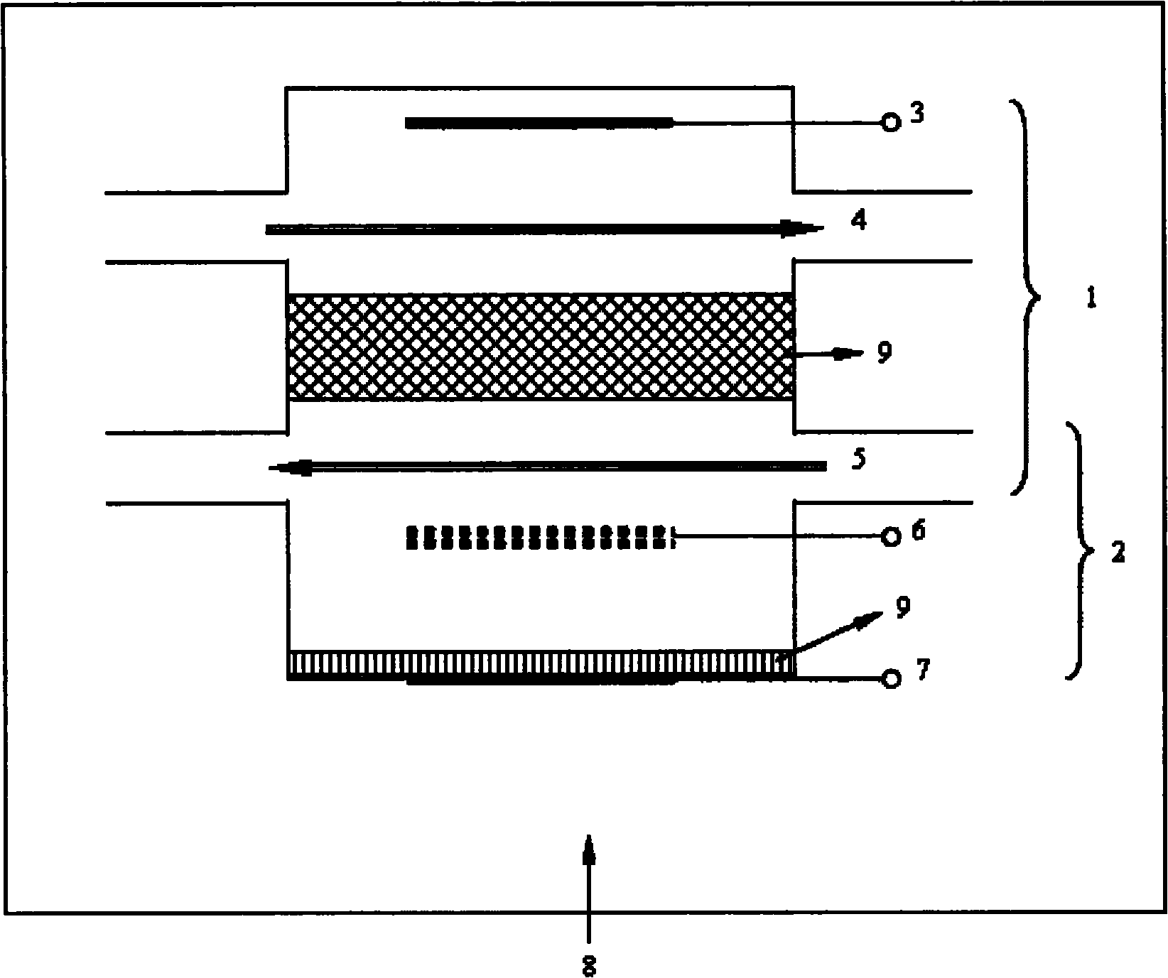
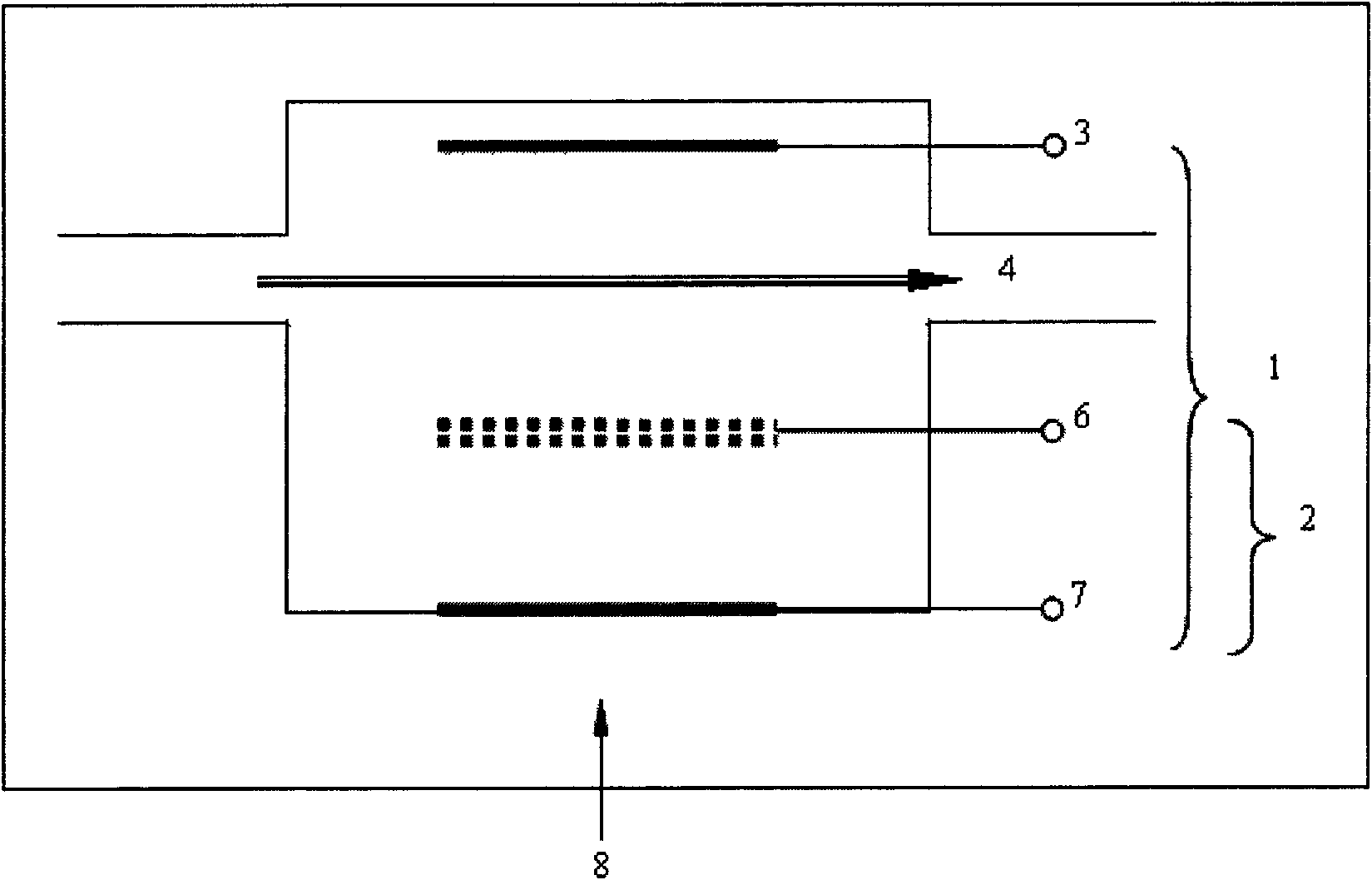
[0023] An uninterrupted flow battery with electrosynthesis function includes an electrosynthesis unit 1 and an external power supply unit 2 . Electrosynthesis unit 1 is composed of positive electrode 3 for catalytic oxidation, electrosynthesis electrolyte solution 4, diaphragm 9, negative electrode electrolyte solution 5 and negative electrode 6, wherein electrosynthesis electrolyte solution 4 contains reducing raw materials; power supply unit 2 consists of negative electrode 6, negative electrode electrolyte Solution 5, diaphragm 9, catalytic oxygen reduction electrode 7 and gas or air 8 containing oxygen; diaphragm 9 can be used between electrosynthesis electrolyte solution 4 and negative electrode electrolyte solution 5, and between negative electrode electrolyte solution 5 and catalytic oxygen reduction electrode 7 Separation; the electrosynthesis unit 1 and the power supply unit 2 are connected through a common negative pole 6 .

[0024]Sintered nickel oxide is used as po...

example 2

[0026] Using graphitized carbon felt as the catalytic oxidation positive electrode 3, the negative electrode 6 uses graphite as the current collector, graphitized carbon felt as the catalytic interface, and the full liquid phase electrode pair V(III) / V(II) as the active material, catalytic oxidation of the positive electrode 3 The negative electrode 6 is separated by an anion exchange membrane 9 to form an electrosynthesis unit 1, and the electrosynthesis electrolyte solution 4 is a 3M HBr+0.1M cystine aqueous solution, wherein cystine is a reducing raw material, water is a solvent, and VBr4 is a supporting electrolyte , negative electrode electrolyte solution 5 is 1MV(III)+3M H 2 SO 4 Aqueous solution; the power supply unit consisting of the negative electrode 6 and the oxygen reduction electrode 7 directly uses an anion exchange membrane to separate the two electrodes, and the oxygen-containing gas is passed into the oxygen reduction electrode 7 of the power supply unit at a...


PUM


Abstract

The invention discloses an uninterrupted chemical battery with electrosynthesis function. The uninterrupted chemical battery consists of an anode for catalytic oxidation, a cathode, a catalytic oxygen reduction electrode and flowing electrolyte, wherein the anode for the catalytic oxidation and a fluid cathode form an electrosynthesis unit of which positive electrolyte / negative electrolyte can be separated by a diaphragm and a diaphragm-free single fluid battery structure also can be adopted; meanwhile, the cathode and the oxygen reduction electrode form an uninterrupted power supply unit of which two electrodes can be separated by a diaphragm and a diaphragm-free battery structure also can be adopted. When the electrosynthesis unit is operated in a charged state, the power supply unit extracts electricity obtained by the cathode through the electrosynthesis unit by utilizing unlimited oxygen-containing gases as electric discharge active materials of the oxygen reduction electrode and supplies the power to outside. The electrolyte continuously and circularly flows between a storage tank and the battery under the drive of a liquid pump. By combining continuous electrosynthesis operation, the electrochemical combined system can continuously electro-synthesize products and is used as an uninterrupted chemical power supply simultaneously so as to fulfill the aims of electric power storage, voltage stabilization, power saving and gain.

Description

technical field [0001] The invention relates to a combination principle and construction method of a new type of uninterruptible power supply, in particular to the principle and preparation of an uninterruptible chemical battery with electrosynthesis function, which belongs to the field of chemical industry and can be used as a voltage stabilizing battery with electrosynthesis function Power supply or rectifier, widely used in electronics industry, electrosynthesis industry, electric power, mining and metallurgy and other fields. Background technique [0002] At present, my country's energy supply is becoming increasingly tense, especially electric energy. In recent years, there have been large-scale power shortages and power cuts in many cities and regions. One of the main reasons for the power shortage is the contradiction between the rapid growth of my country's economy and the limited growth of energy supply. Among them, industries, especially electrolytic aluminum, ste...

Claims


Application Information

Patent Timeline
IPC IPC(8): H01M6/32H01M6/42
CPCY02E60/12
Inventor 文越华程杰张立徐艳刘学虎曹高萍杨裕生
Owner NO 63971 TROOPS PLA
Learn More